← Selected Work VOD-2025 · Metal AM · Generative Design

Void

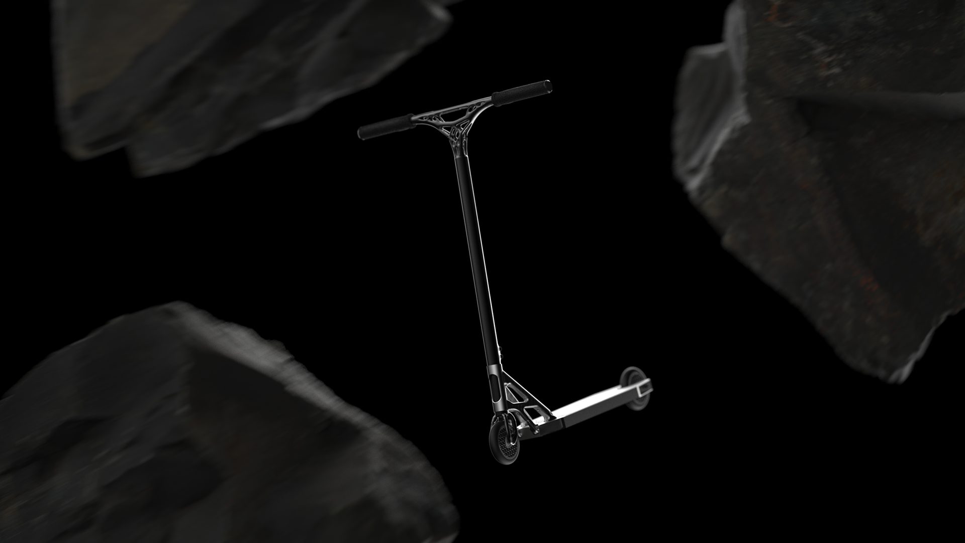
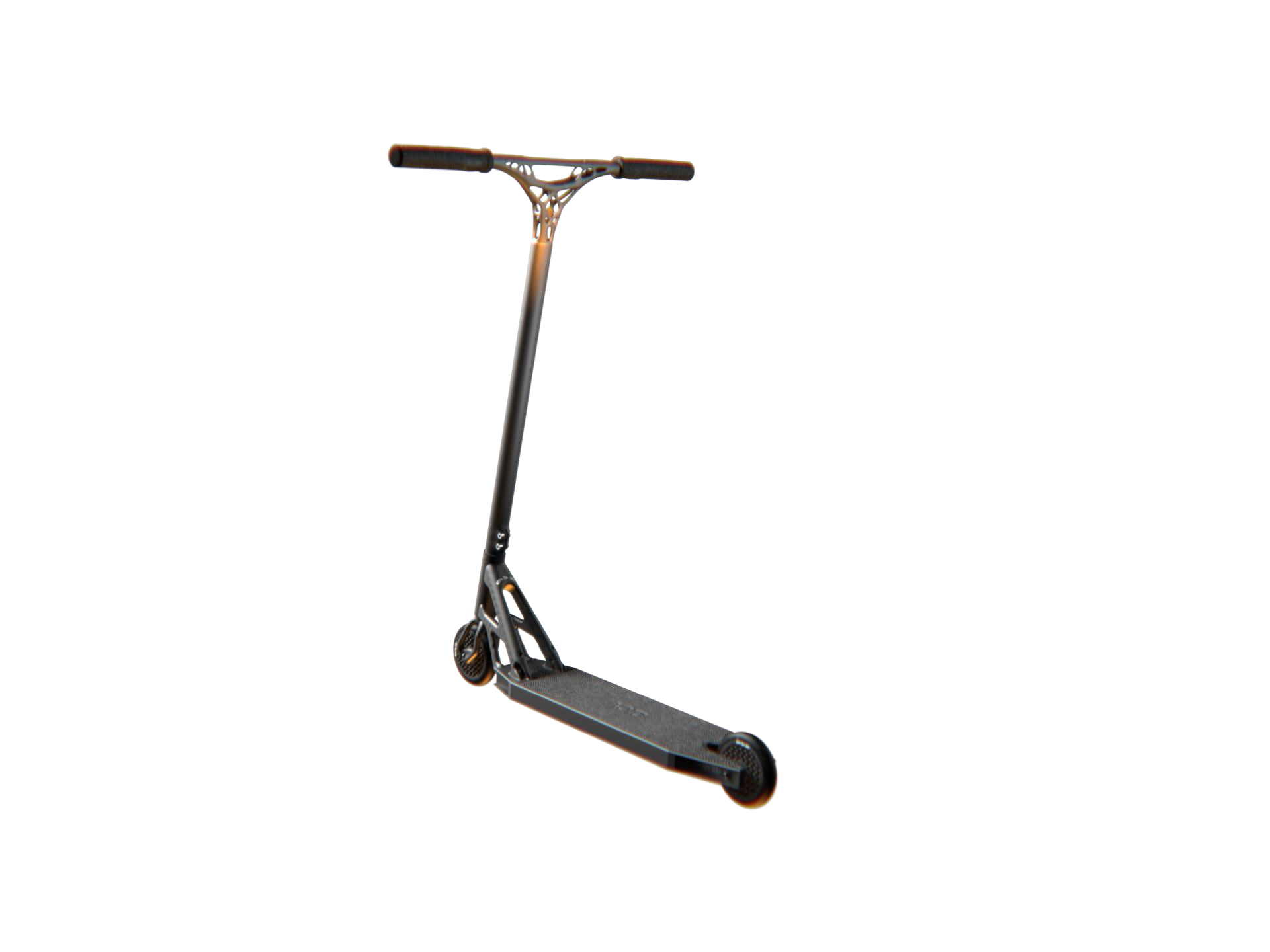
The world’s lightest stunt scooter, engineered with metal additive manufacturing.

RoleDesign & Optimization
Year2025
DisciplineMetal AM · Lattices
Total mass2.21 kg
Void — ride the void, the opening lockup

THE WORLD’S LIGHTEST SCOOTER

The Void stunt scooter

Challenge

High-Performance
Stunt Scooter

Develop a scooter built specifically for the demanding discipline of stunt riding, where every component has to deliver superior response and reliability under the intense dynamic loads and impacts of acrobatic use.

Extreme
Lightness

Explore the limits of mass reduction for a metal stunt scooter, with the ambition of building a vehicle that competes directly with the lightest on the market today, radically improving the rider's agility and manoeuvrability.

Structural
Strength

Make sure the pursuit of maximum lightness never compromises structural integrity or durability, using advanced materials and optimization for exceptional resistance to the most severe loads.

Innovation Through
Additive Manufacturing

Harness the disruptive potential of metal AM and generative design to realize optimized organic forms and functional lattice microstructures, going beyond the limits of traditional manufacturing methods.

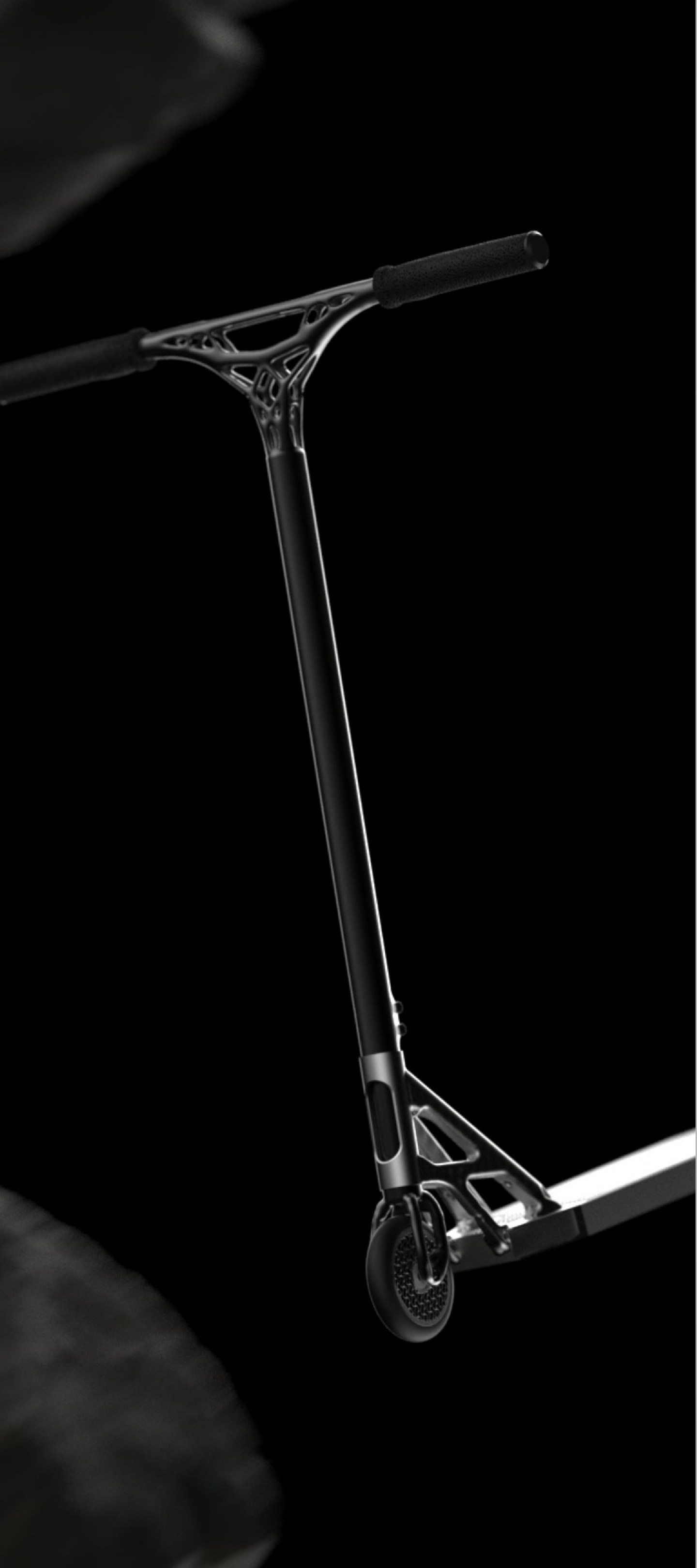
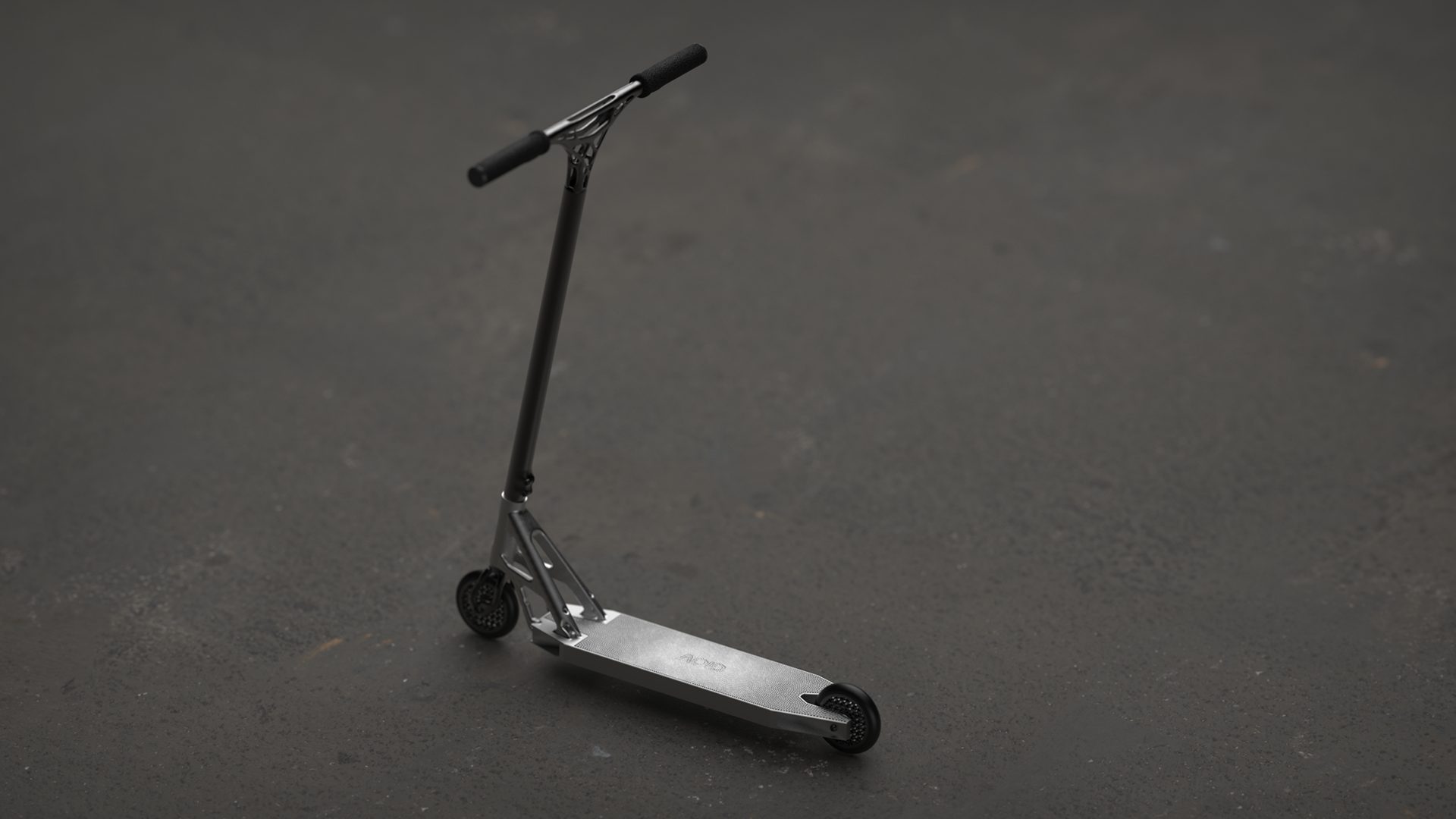
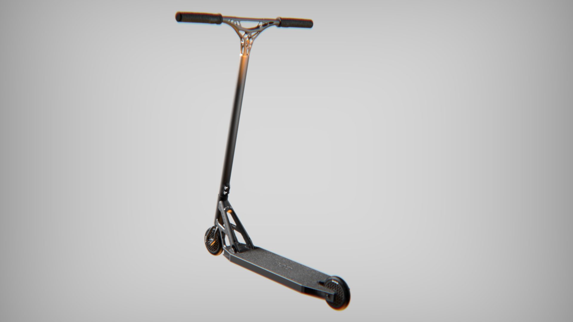
The Void scooter, full view

Ultra-lightweight performance (< 2.5 kg)

Under 2.5 kg, with exceptional stunt durability

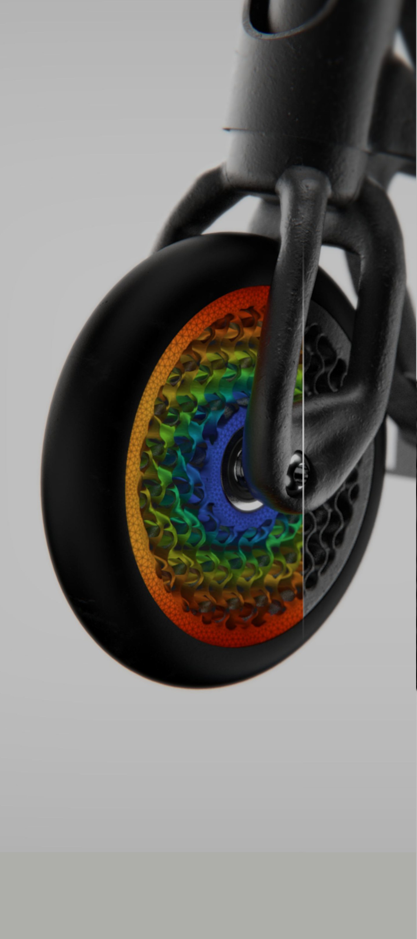
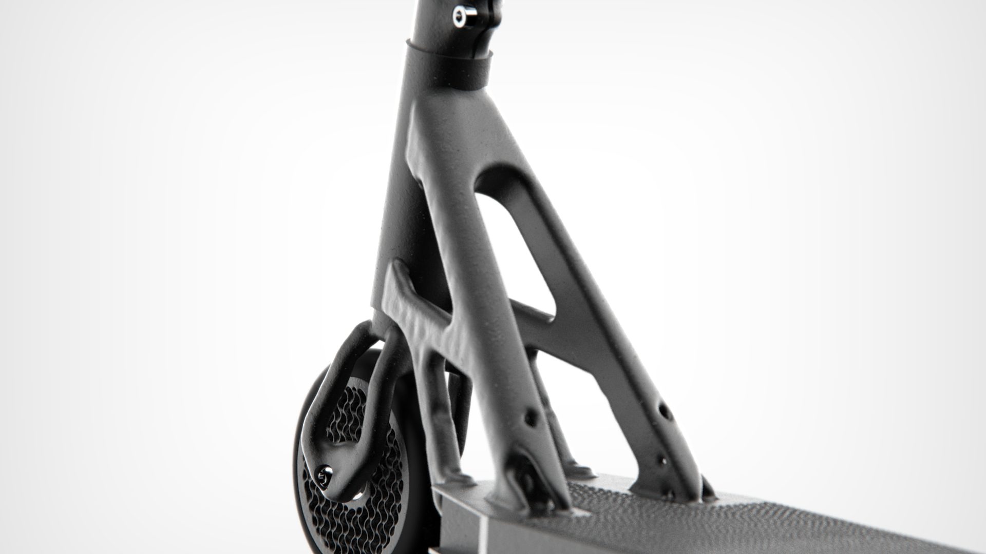
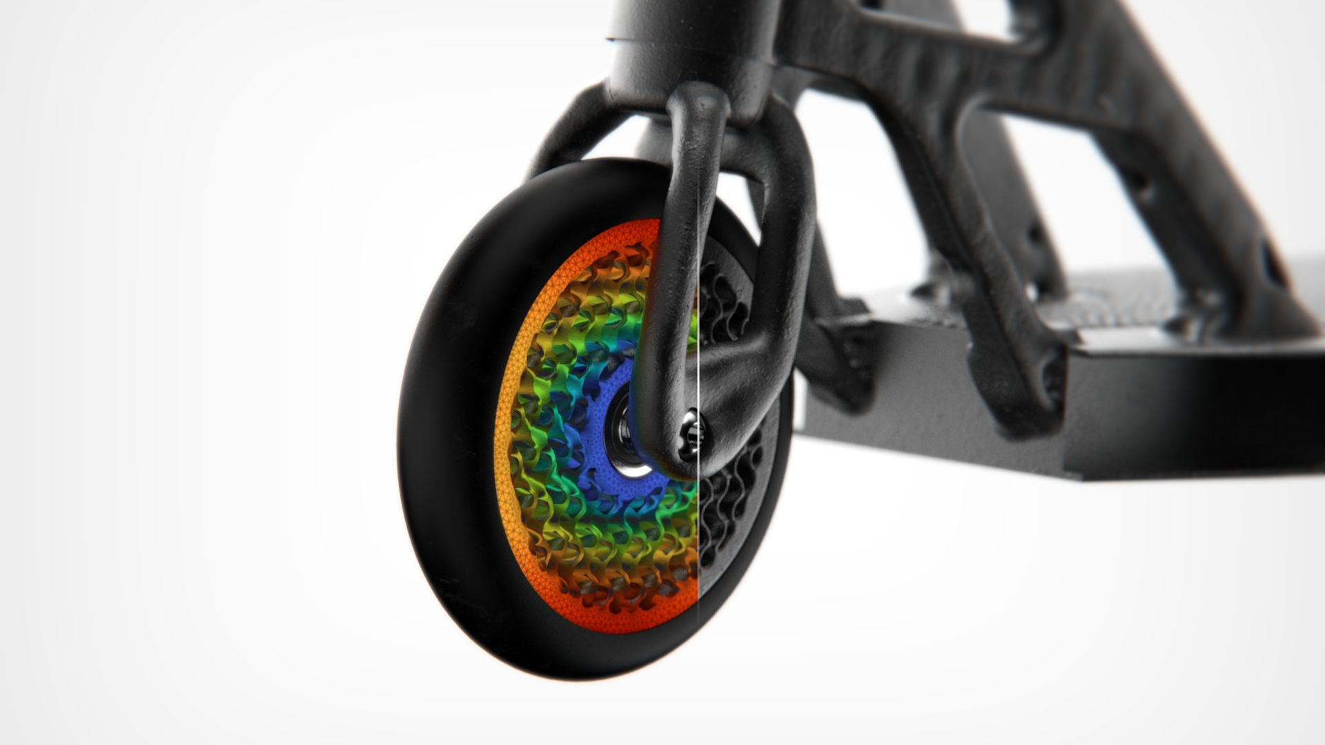
Topology-optimized wheel with its internal lattice

Topology optimization & lattices

Topology optimization for the macrostructure and internal lattices, for weight and functional comfort.

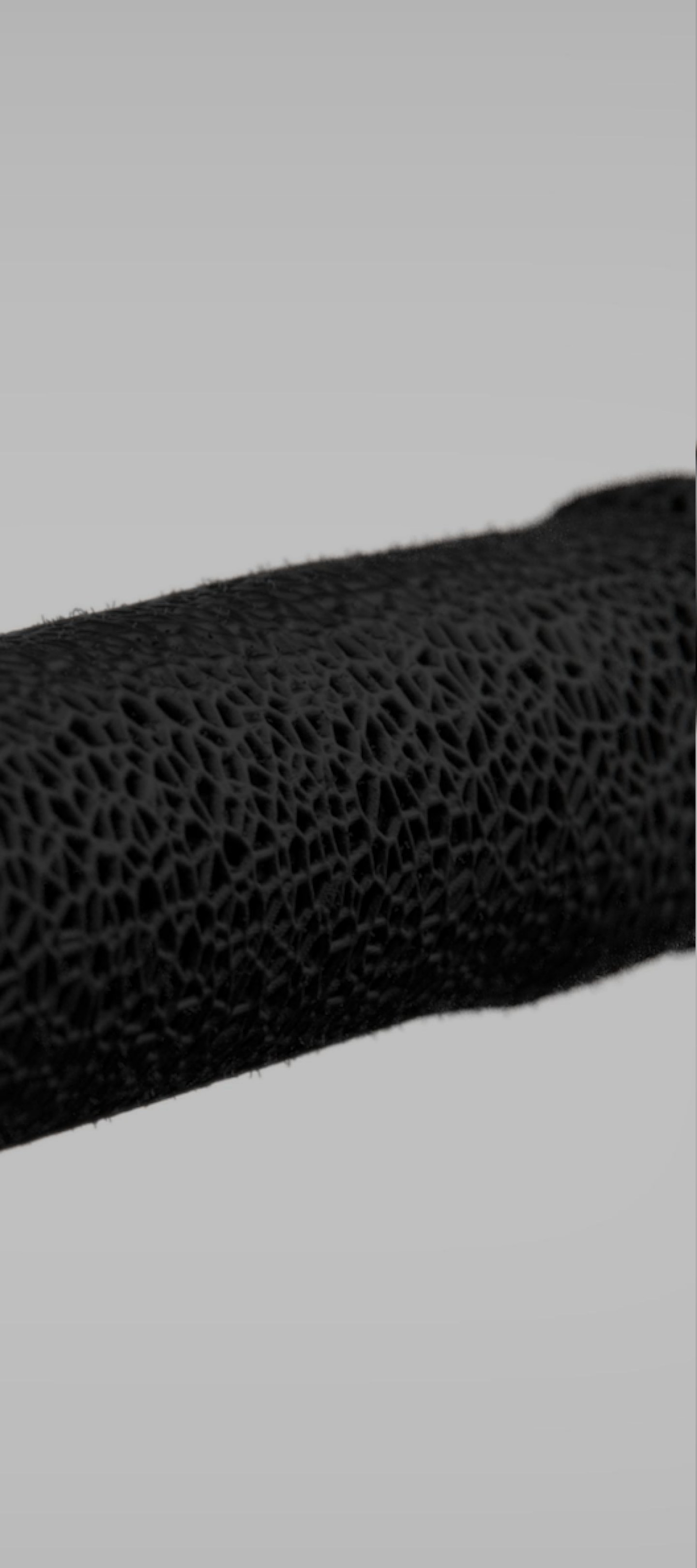
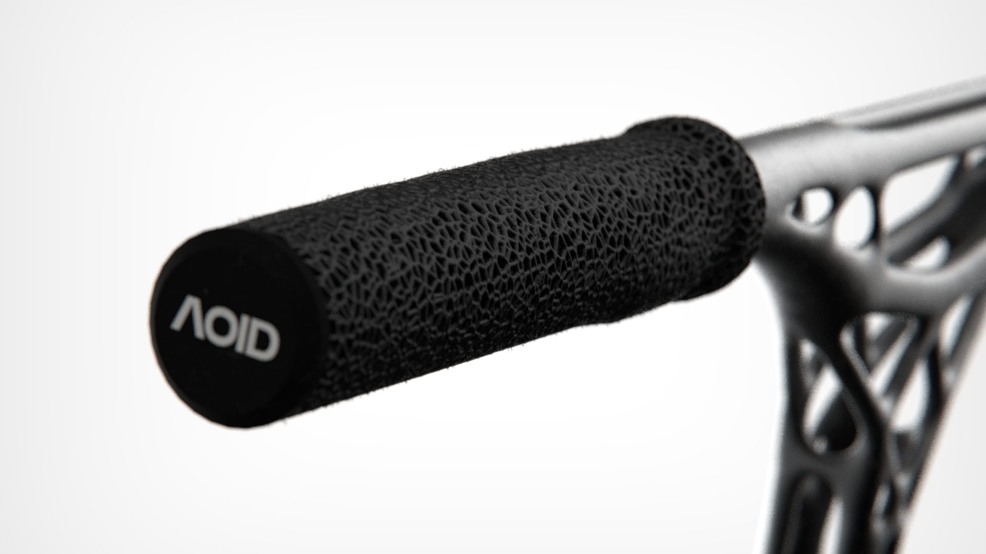
Voronoi lattice surface on the handlebar grip

Advanced AM

Metal additive manufacturing for complex, optimized geometries

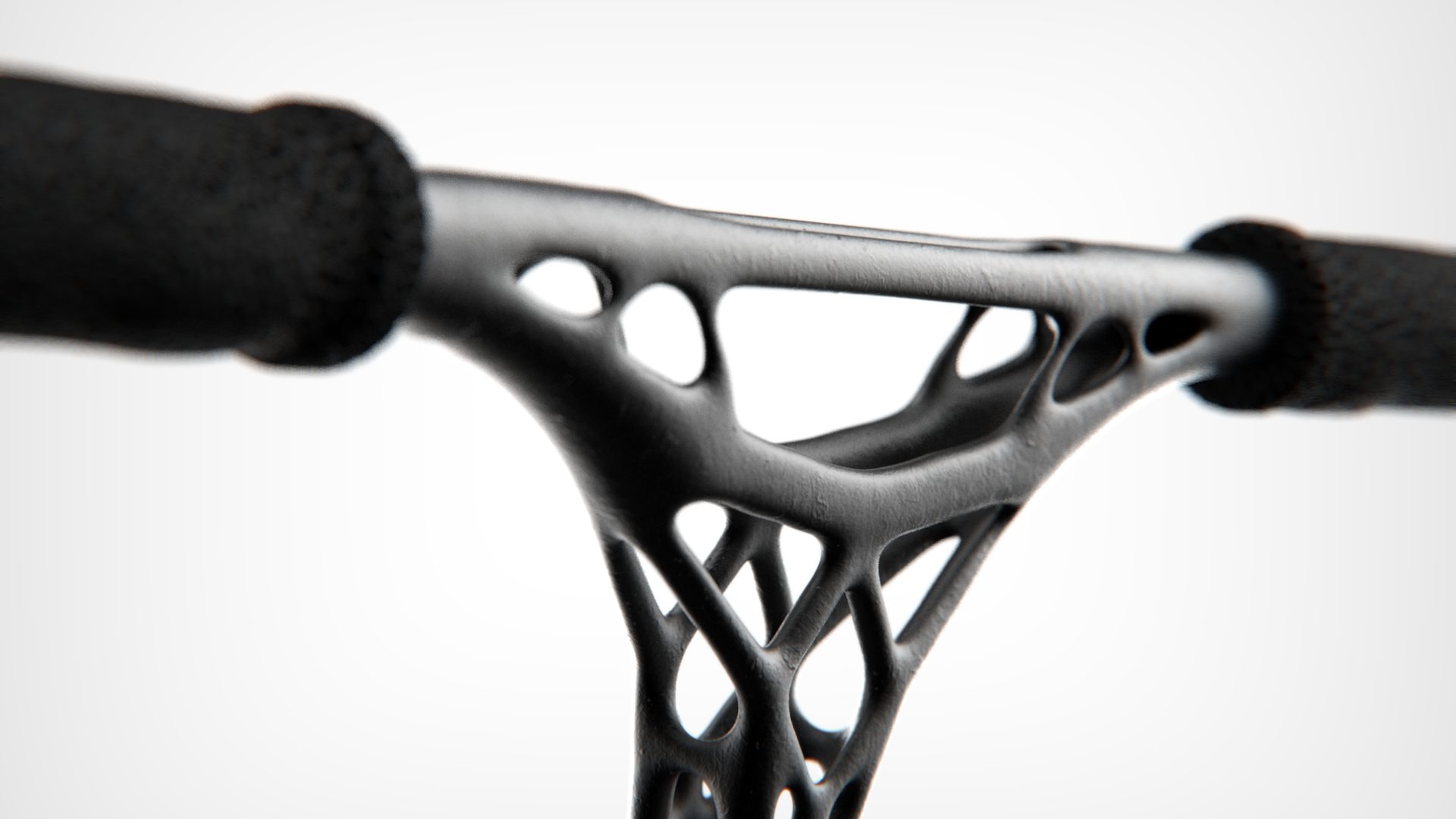
Organic printed structure of the handlebar

Distinctive "Engineered Raw" aesthetic

"Engineered Raw" visual identity: organic aesthetics derived directly from the optimization and from AM technology.

Methodology

Initial modelling

Methodology step: initial modelling
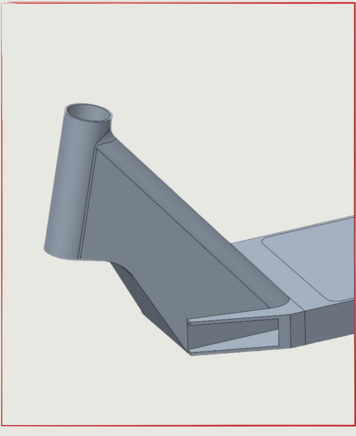
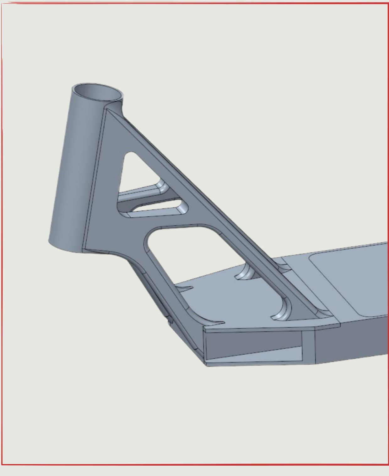
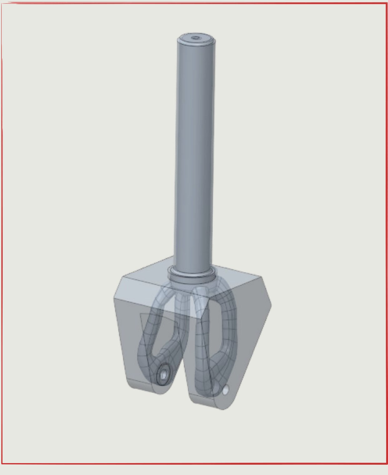
We start from initial design volumes for each key component — deck, fork, handlebar — built in Creo Parametric, respecting the interfaces and standard dimensions of the stunt sector.

Load conditions
(deck)

Methodology step: load conditions, deck
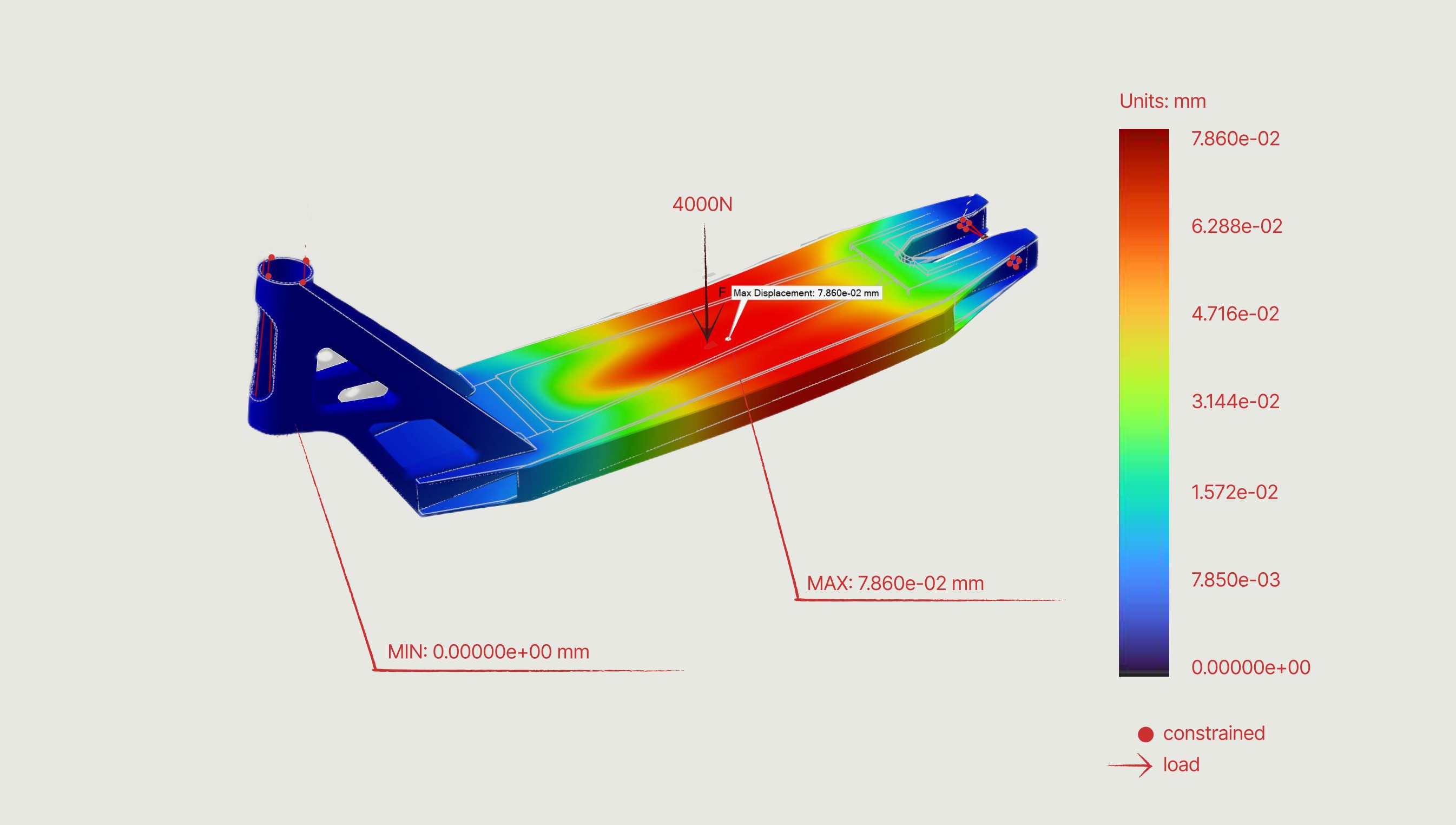
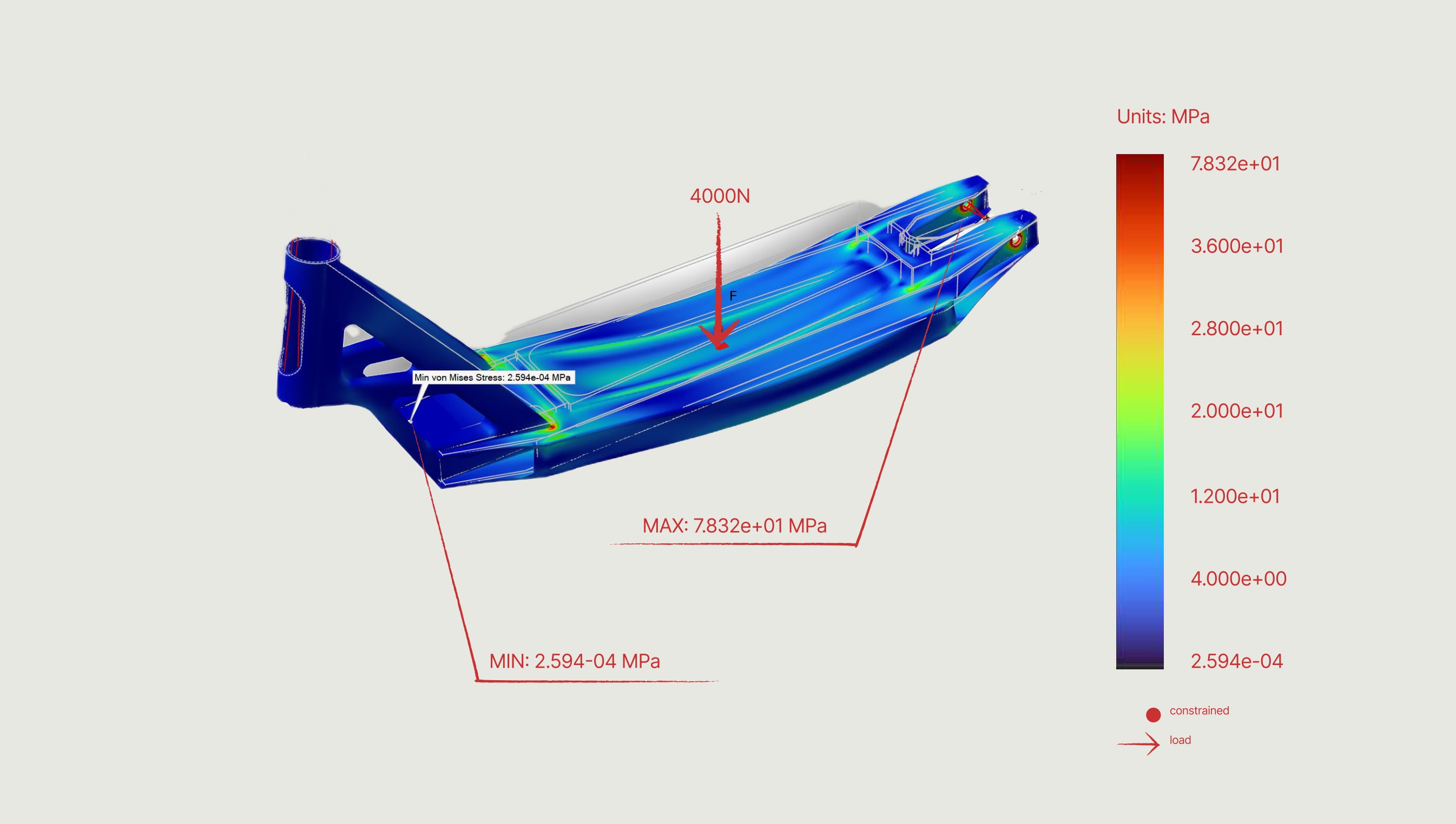
For the deck, 4000 N was applied at the centre to simulate the impact of a jump, with the wheel areas defined as fixed supports for the optimization.

Load conditions
(fork)

Methodology step: load conditions, fork
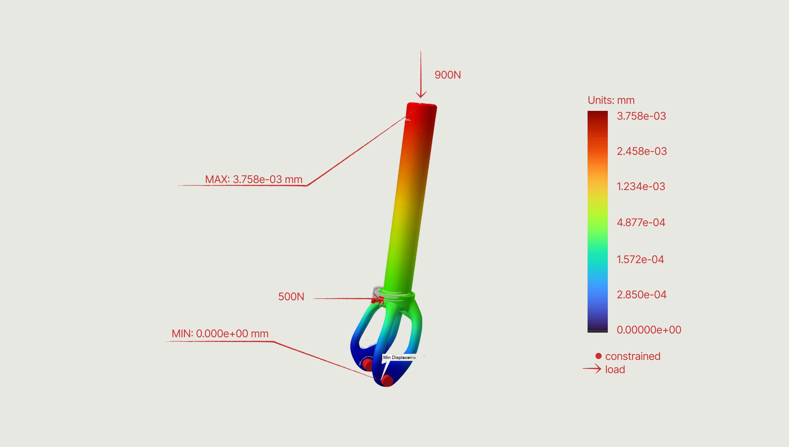
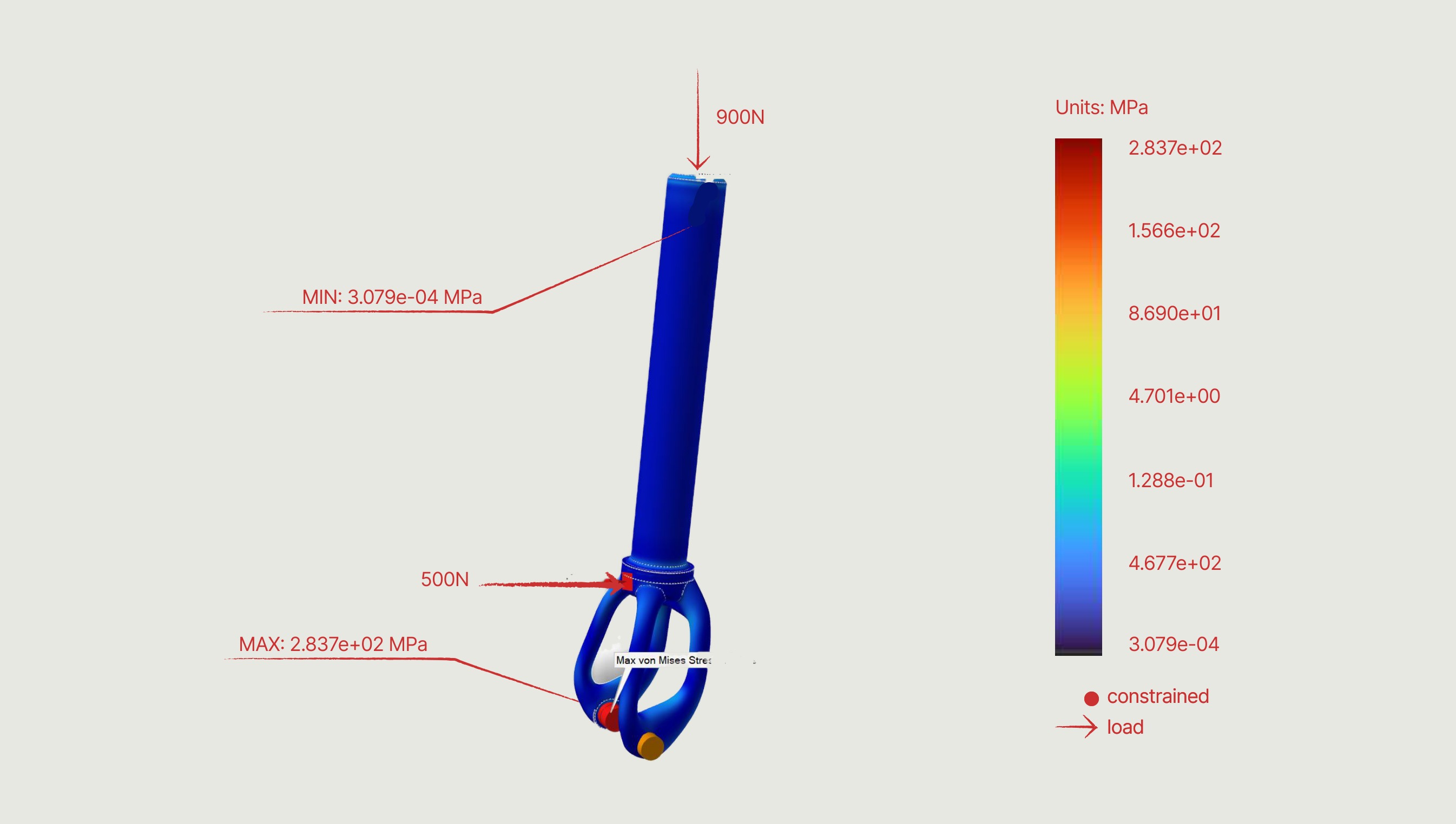
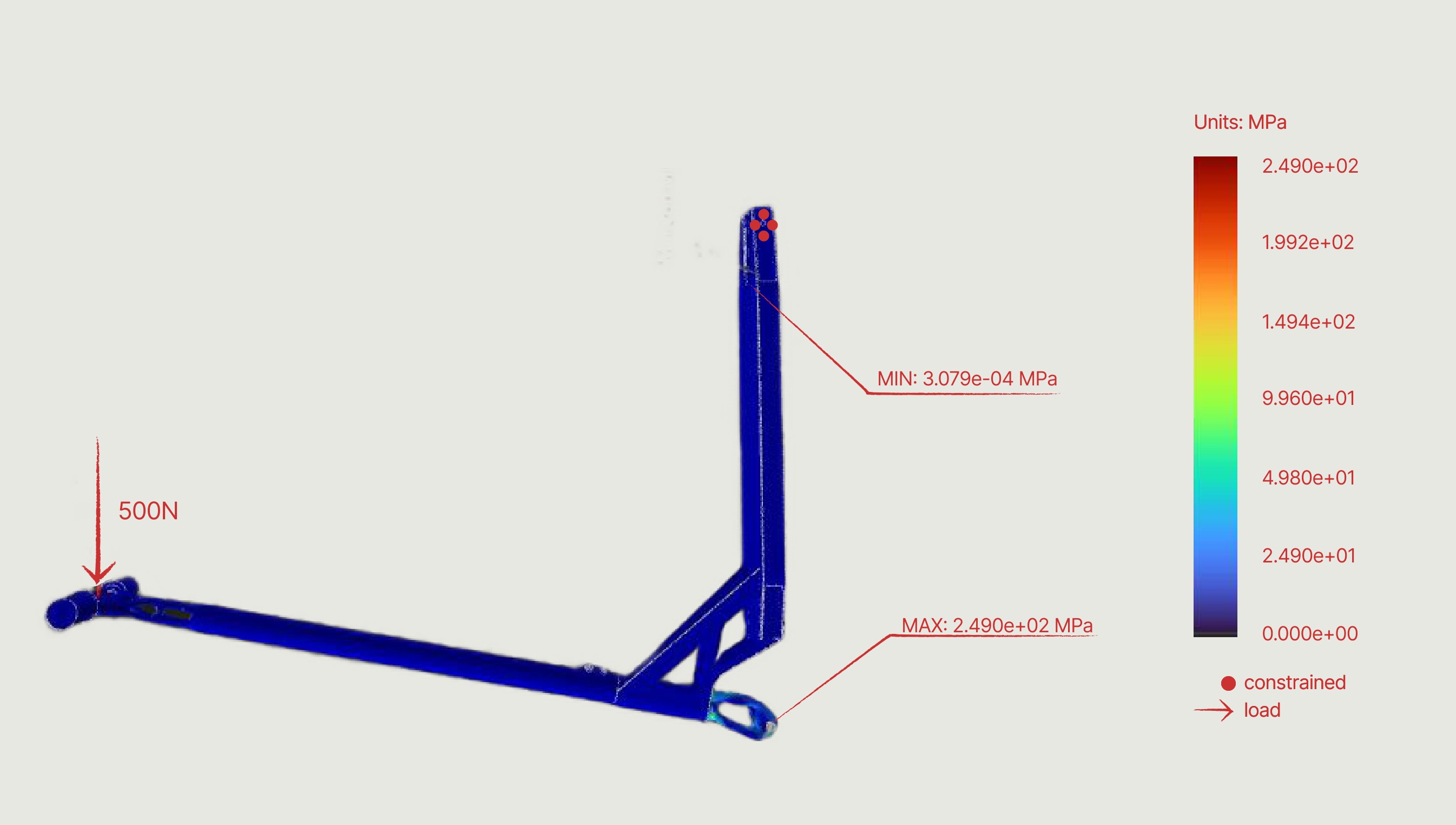
The fork was optimized by applying 900 N at the handlebar area — simulating compression and impact — plus a 500 N frontal load for direct impacts.

Load conditions
(handlebar)

Methodology step: load conditions, handlebar
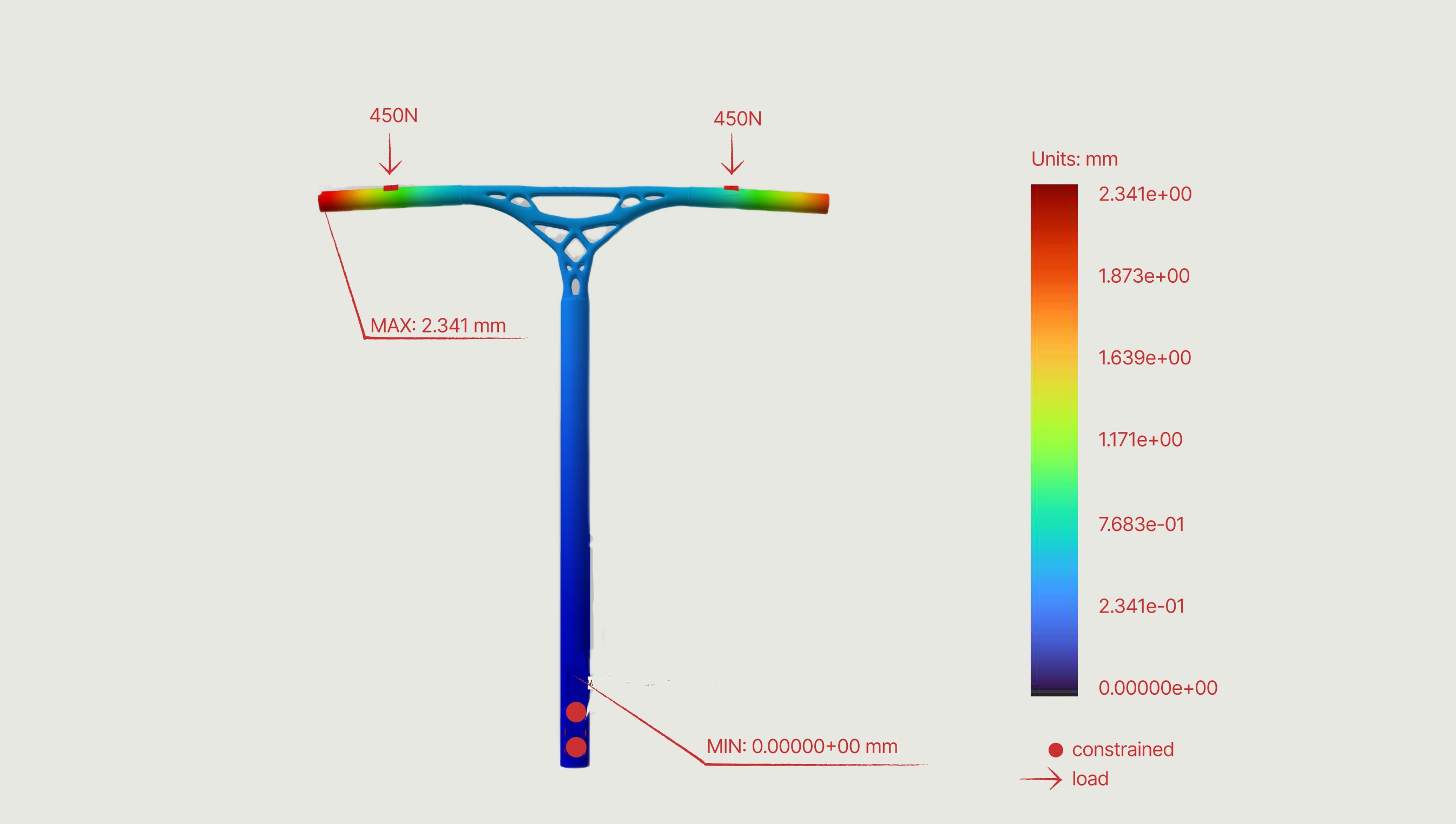
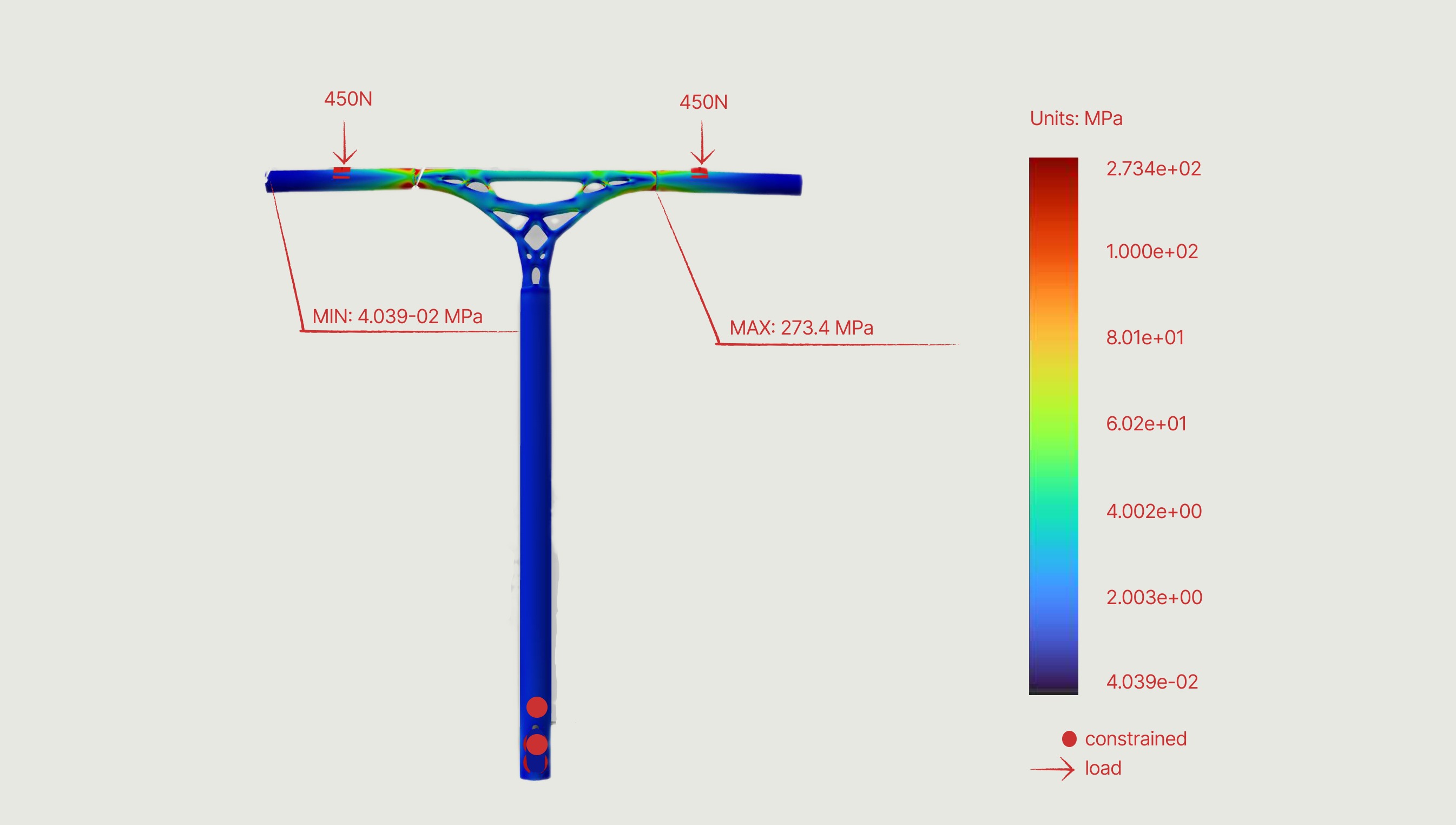
For the handlebar, forces of 450 N were applied at each end with the base fixed to the fork, simulating rider compression and dynamic loads.

Simulation

Deck

The deck takes the whole of a landing. A 100 kg rider is roughly 1 kN standing still, so a dynamic factor of four was applied to reach the impact case: 4000 N distributed across the standing surface, with the wheel mounts held as fixed supports. Sizing to the limit case rather than the static one is what leaves the safety factor intact in normal riding.

Deck — displacement under a 4000 N centre load
Deck — Von Mises stress under a 4000 N centre load

Handlebar

In a bar-spin or a hard pull-up the rider hangs their entire weight off the grips. 900 N was split evenly between the two ends, 450 N each, with the base clamped to the fork — the arrangement that puts the greatest bending moment through the tube and its junction with the clamp.

Handlebar — displacement under 450 N at each end
Handlebar — Von Mises stress under 450 N at each end

Fork

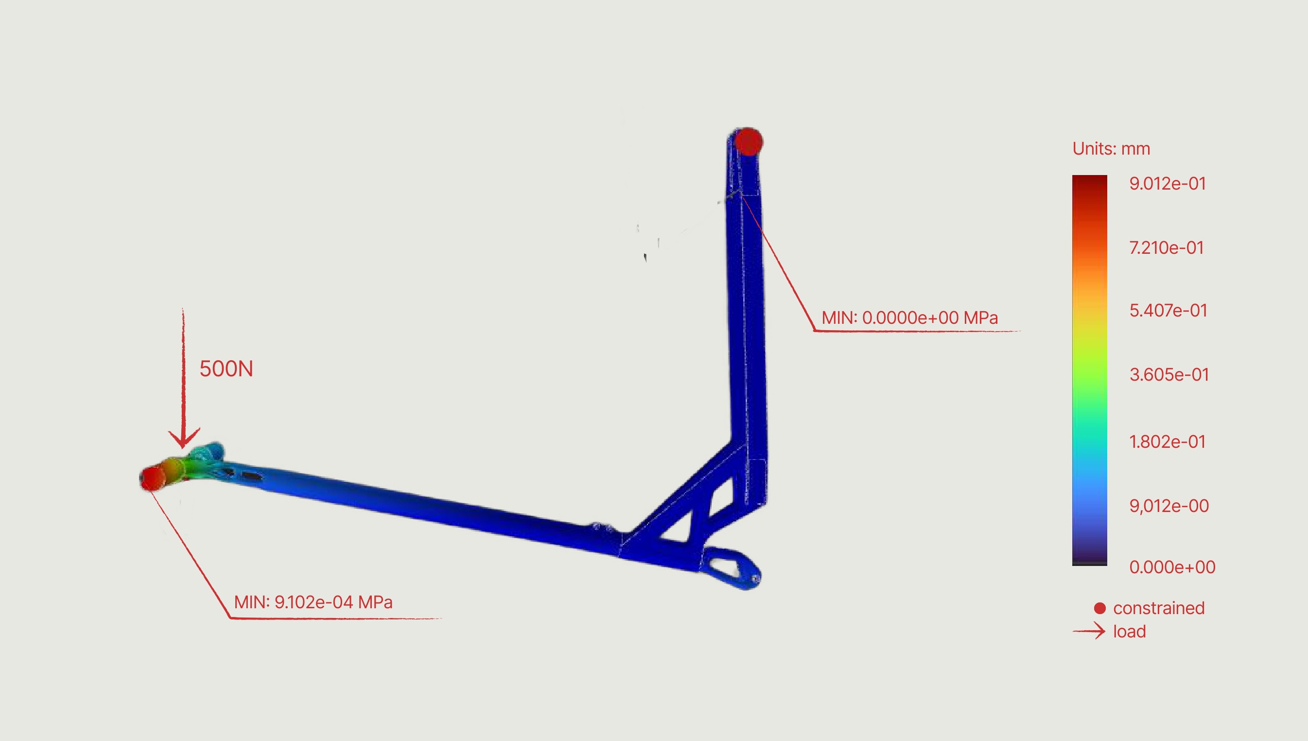
The fork inherits that same 900 N through the steerer, so it was loaded at the handlebar interface rather than in isolation, with a further 500 N frontal component for a direct hit against an obstacle. Constrained at the wheel axle, which is where the load finally goes to ground.
Fork — displacement under 900 N and a 500 N frontal load
Fork — Von Mises stress under 900 N and a 500 N frontal load

Wheels

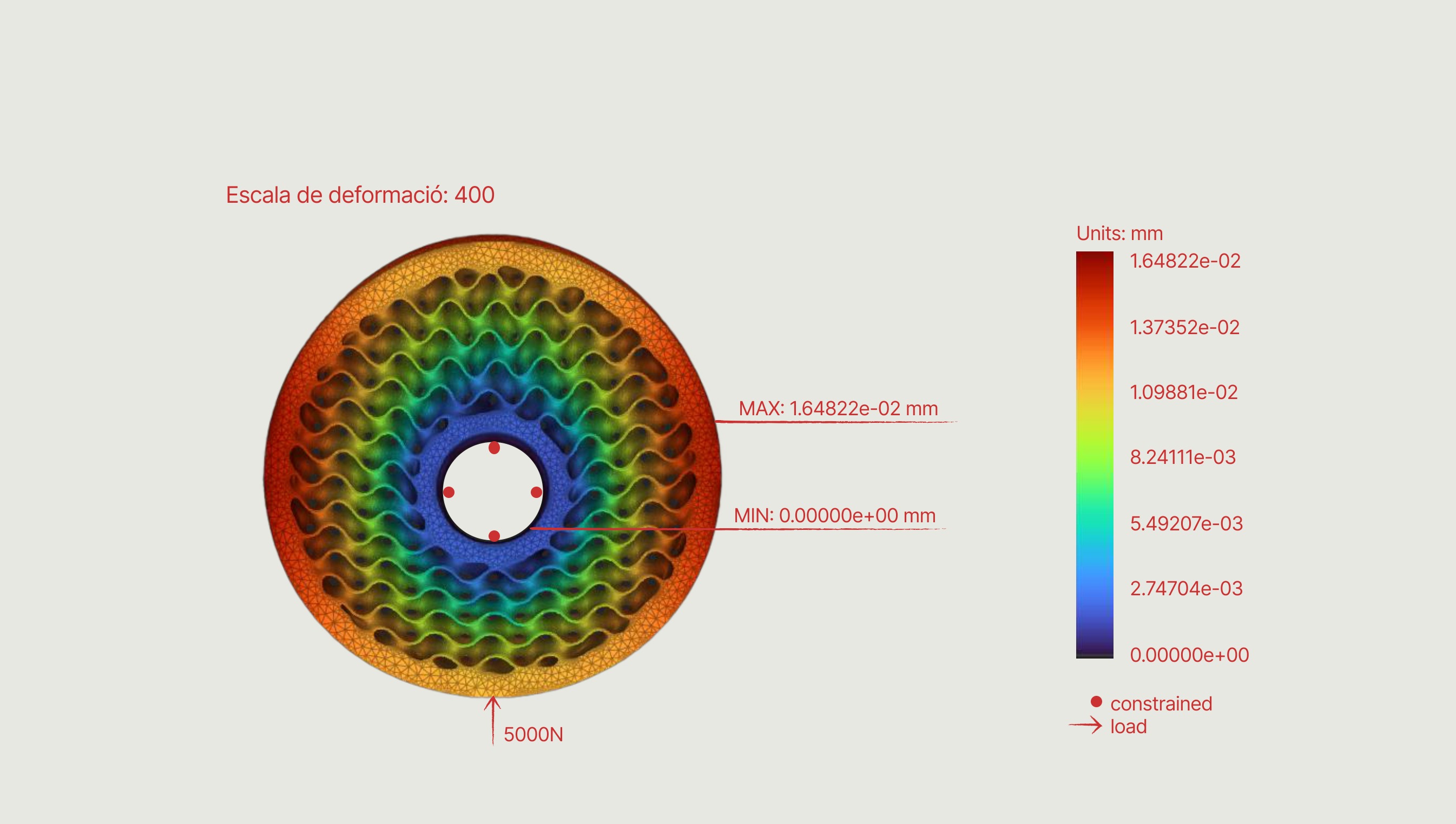
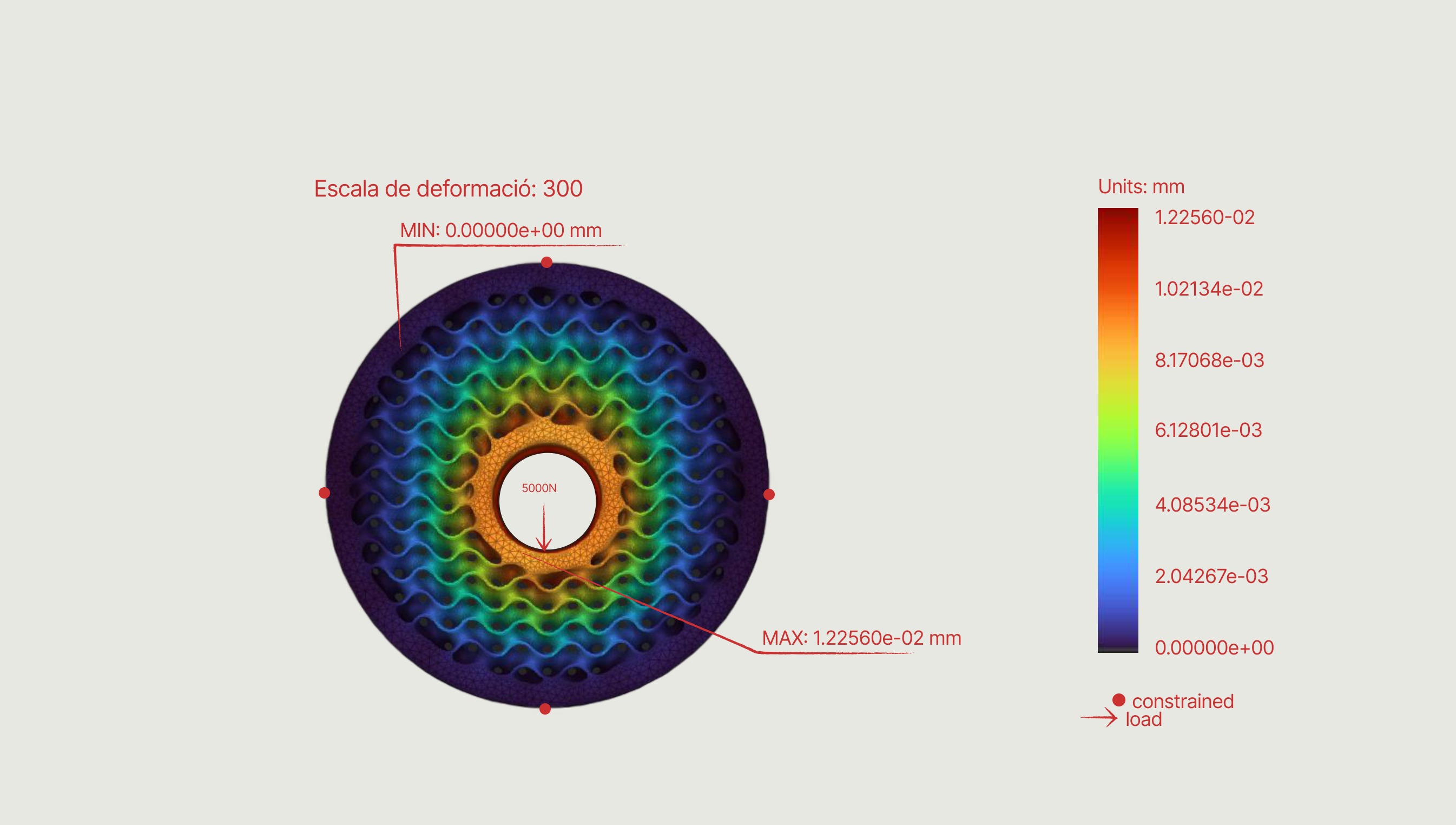
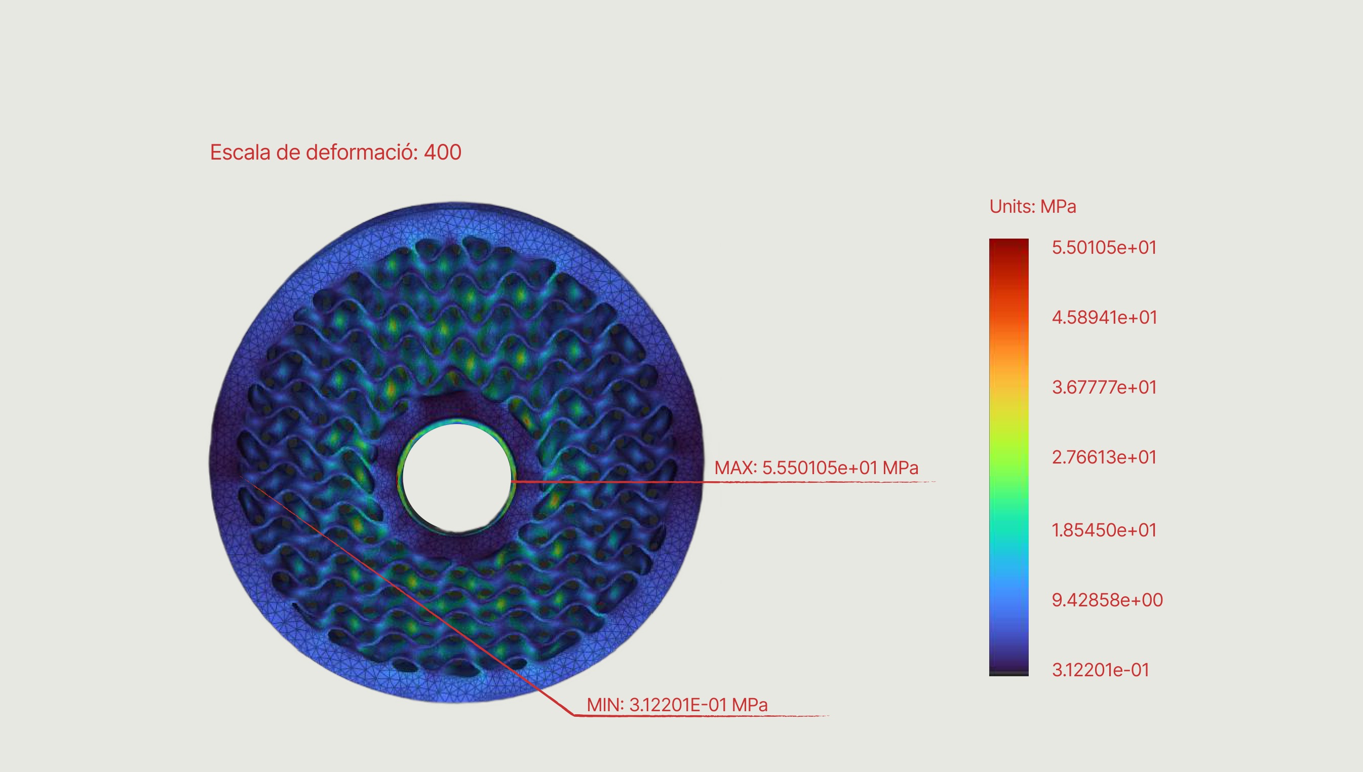
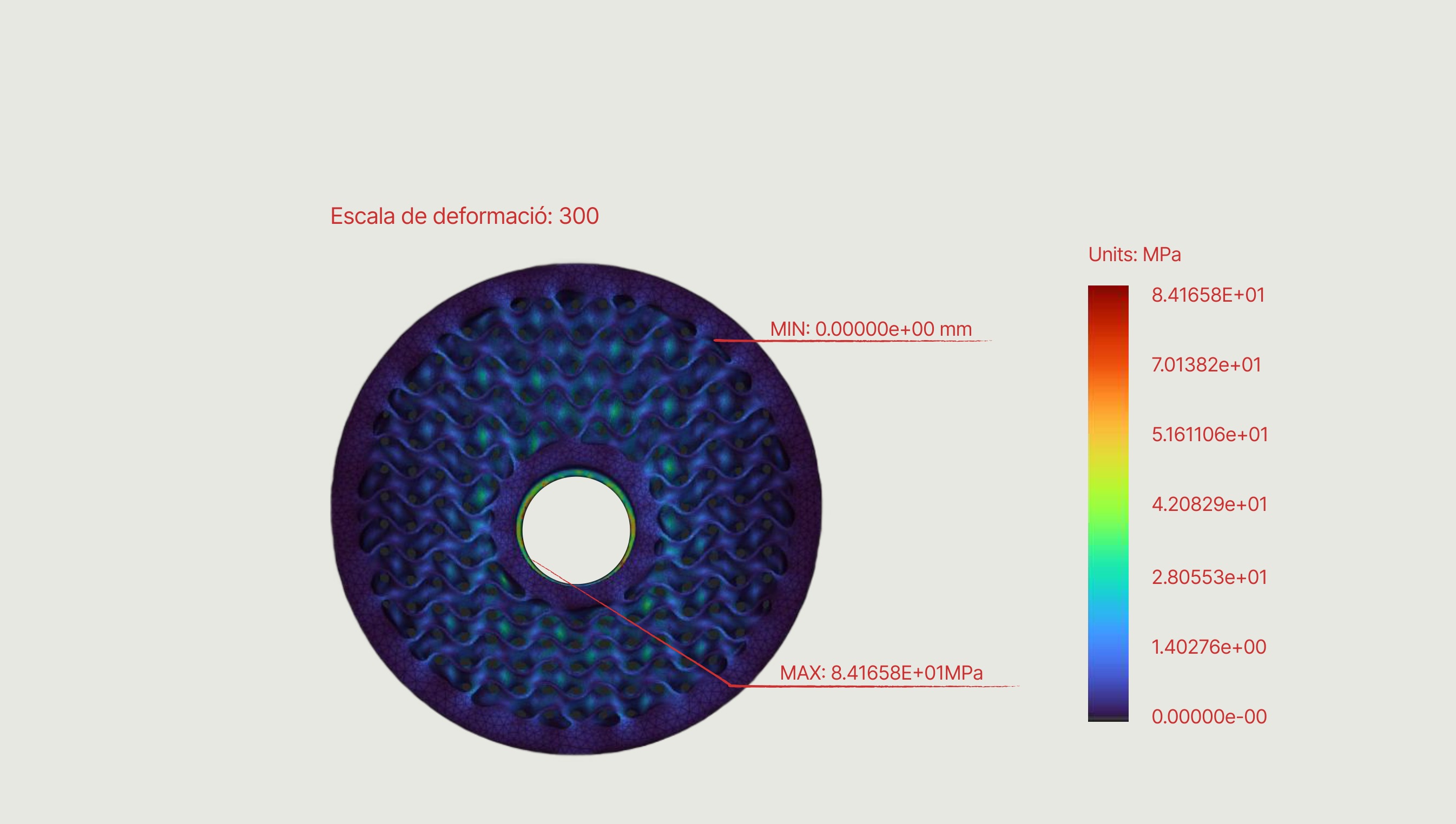
Constrained at the central axle and loaded with a 5000 N reaction from the ground at the contact patch: the peak a single wheel sees landing off a ledge in extreme use, far above anything the rider's static weight alone would produce. Shown at two deformation scales so the mode of deflection is readable.

Wheel — displacement under the 5000 N ground reaction, deformation scale 400
Wheel — displacement under the 5000 N ground reaction, deformation scale 300
Wheel — Von Mises stress under the 5000 N ground reaction, deformation scale 400
Wheel — Von Mises stress under the 5000 N ground reaction, deformation scale 300

Assembly test

The final gate. The complete scooter under the homologation case set out in the brief, with every joint, clamp and interface carrying load at the same time rather than each part being judged on its own. Clearing this test is what qualifies the design as approved.

Full assembly — displacement under a 500 N frontal load
Full assembly — Von Mises stress under a 500 N frontal load

Lattices

Deck

Lattice application: DECK
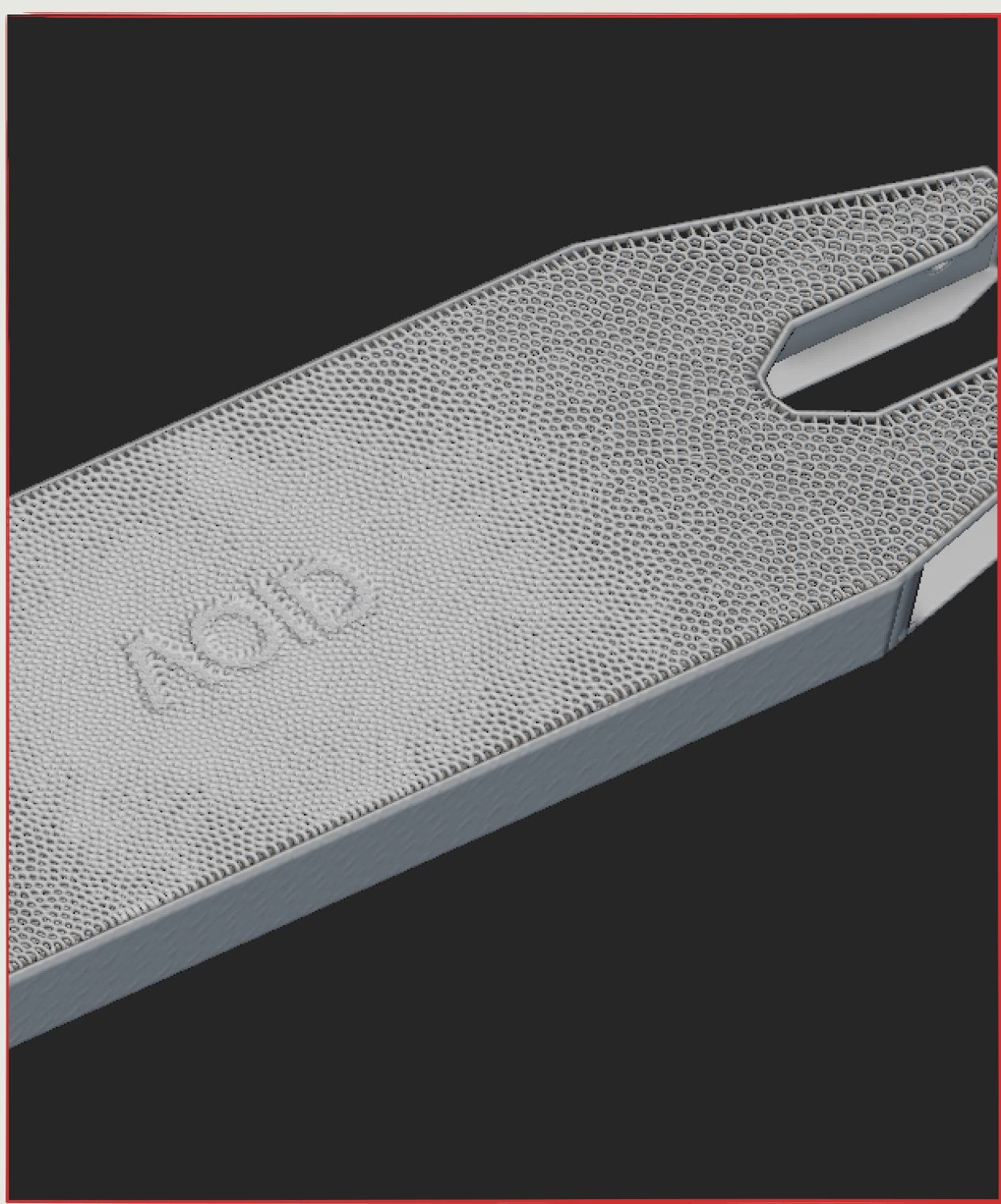
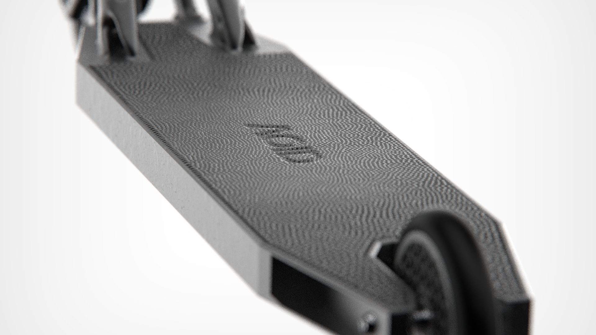
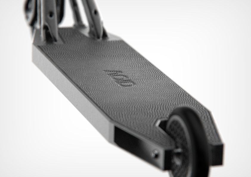
Voronoi pattern on the base deck, derived from the logotype, increasing grip through its irregular texture and helping reduce weight.

Handlebar grips

Lattice application: HANDLEBAR GRIPS
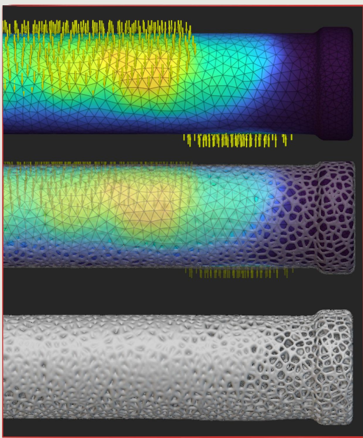
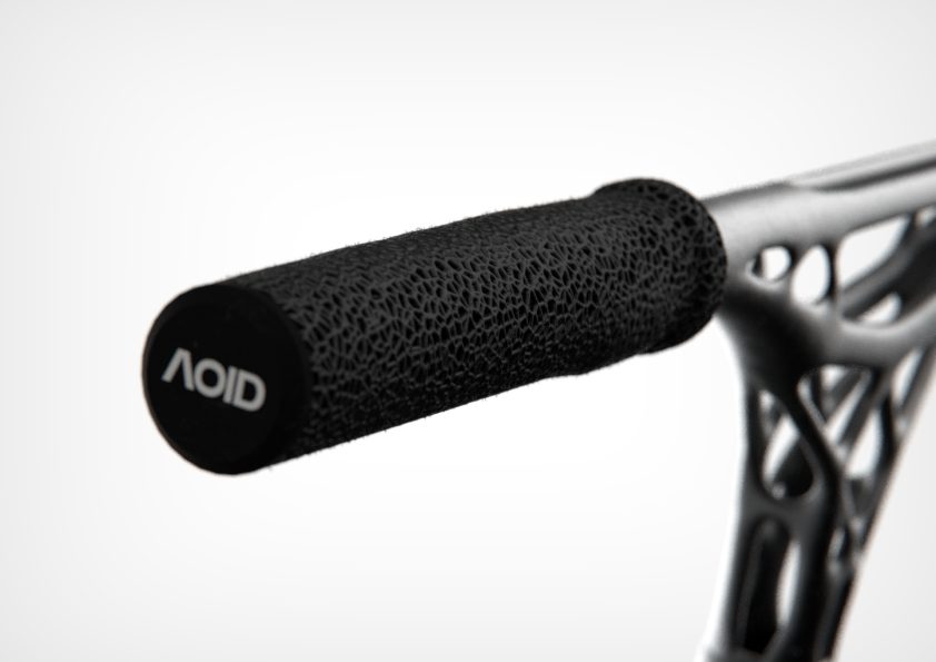
Voronoi pattern on the handlebar grip, derived from the simulation of hand forces, improving the tactile feel.

Fork

Lattice application: FORK
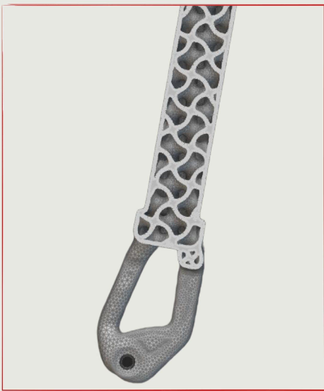
Gyroid structure inside the fork, cutting weight while increasing multidirectional strength.

Wheel

Lattice application: wheel
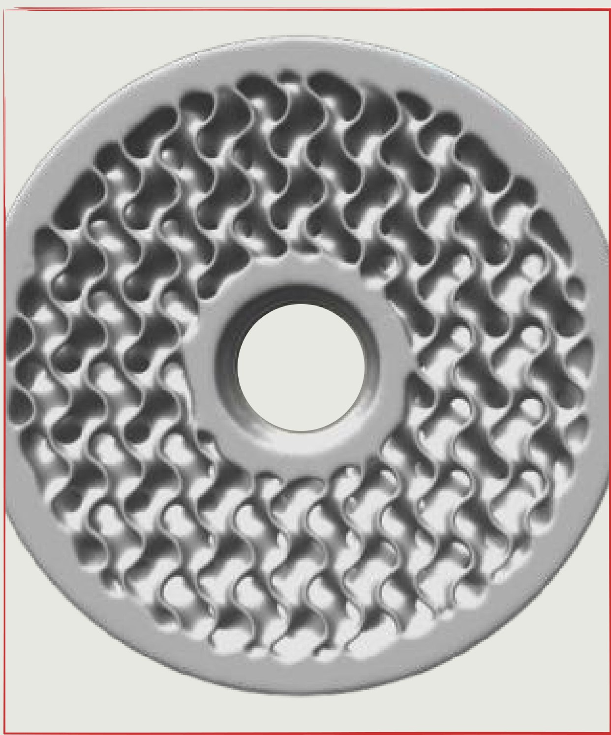
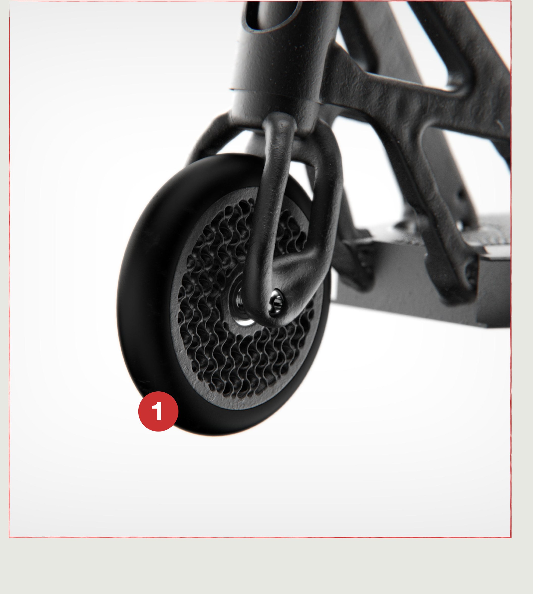
Gyroid structure in the wheel rim, optimized to maximize compressive strength and minimize weight.

Parts

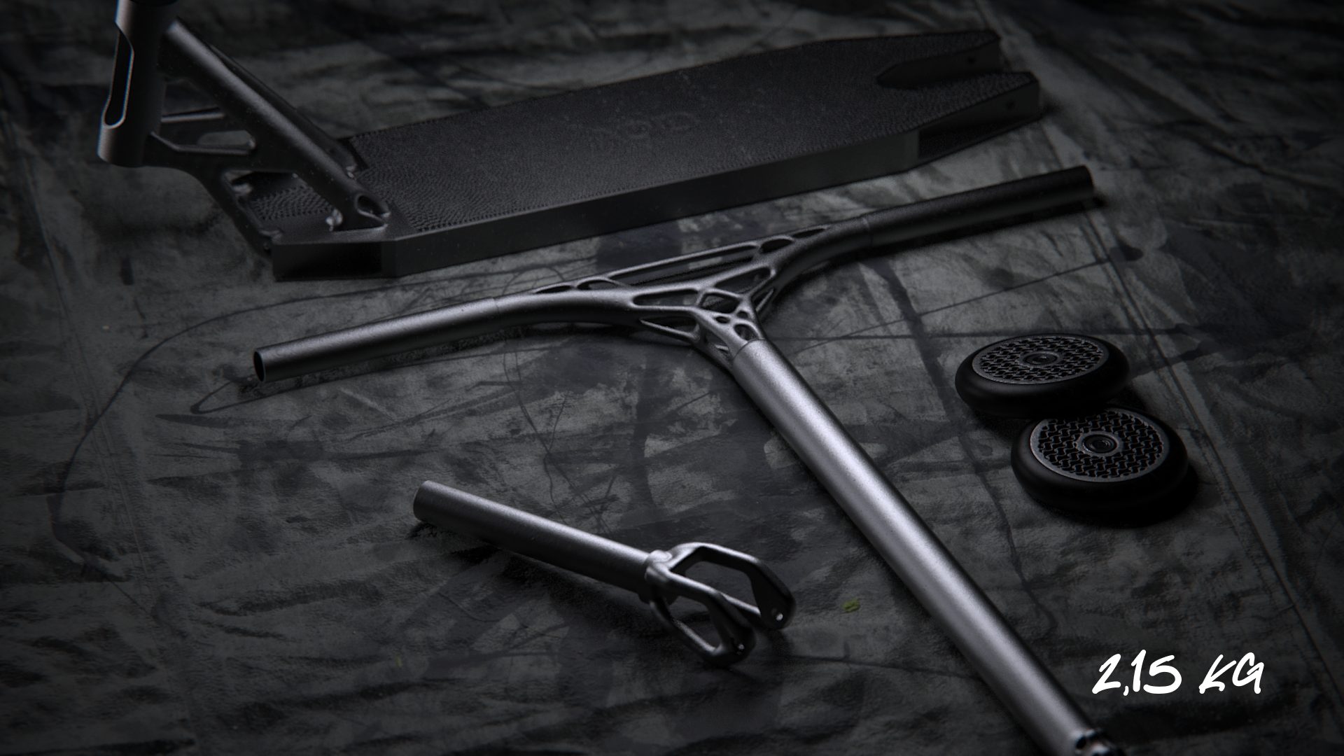
The Void deck

Deck

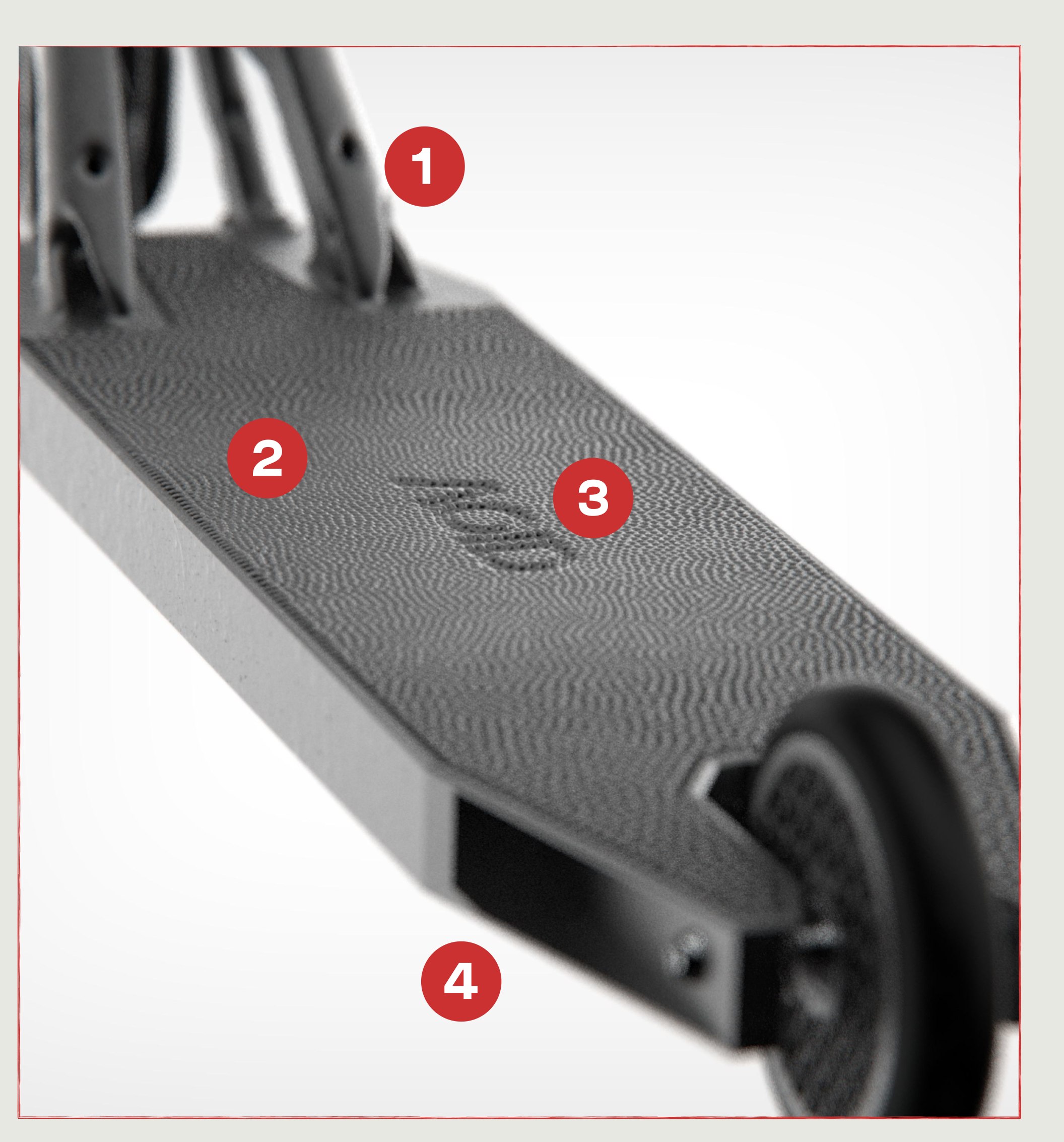
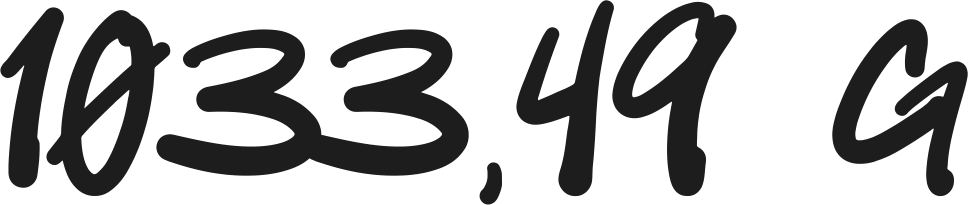
Deck, 1033.49 g
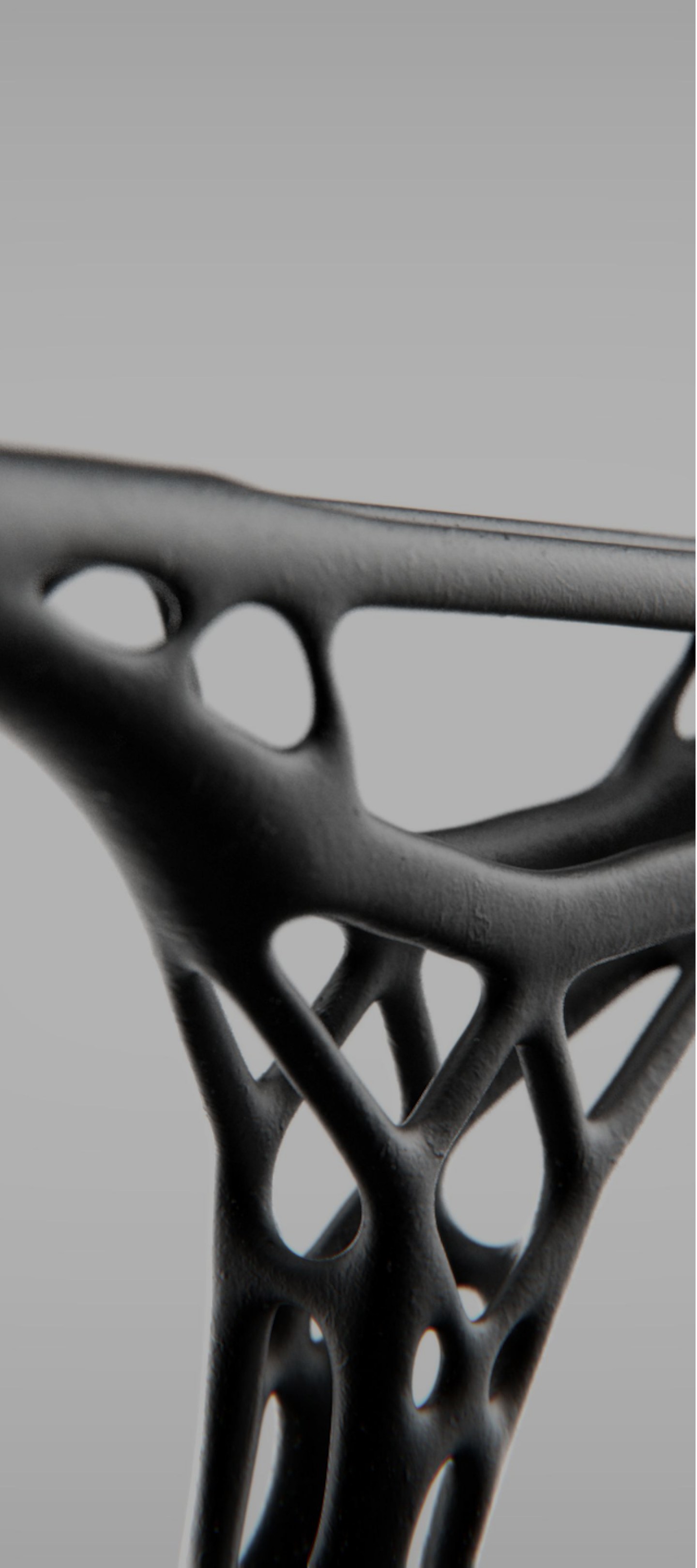
  1. Base-to-handlebar junction: an organic form resulting directly from topology optimization.
  2. Surface redesigned with a Voronoi pattern: better grip from the irregular texture, and weight saved through the voids between cells.
  3. Logo-driven design: a Voronoi pattern generated from the logotype, integrated into the surface and propagated across it along its own geometry.
  4. Hollow internal structure: optimized geometry that keeps the rigidity with a significant reduction in weight.
The Void handlebar

Handlebar

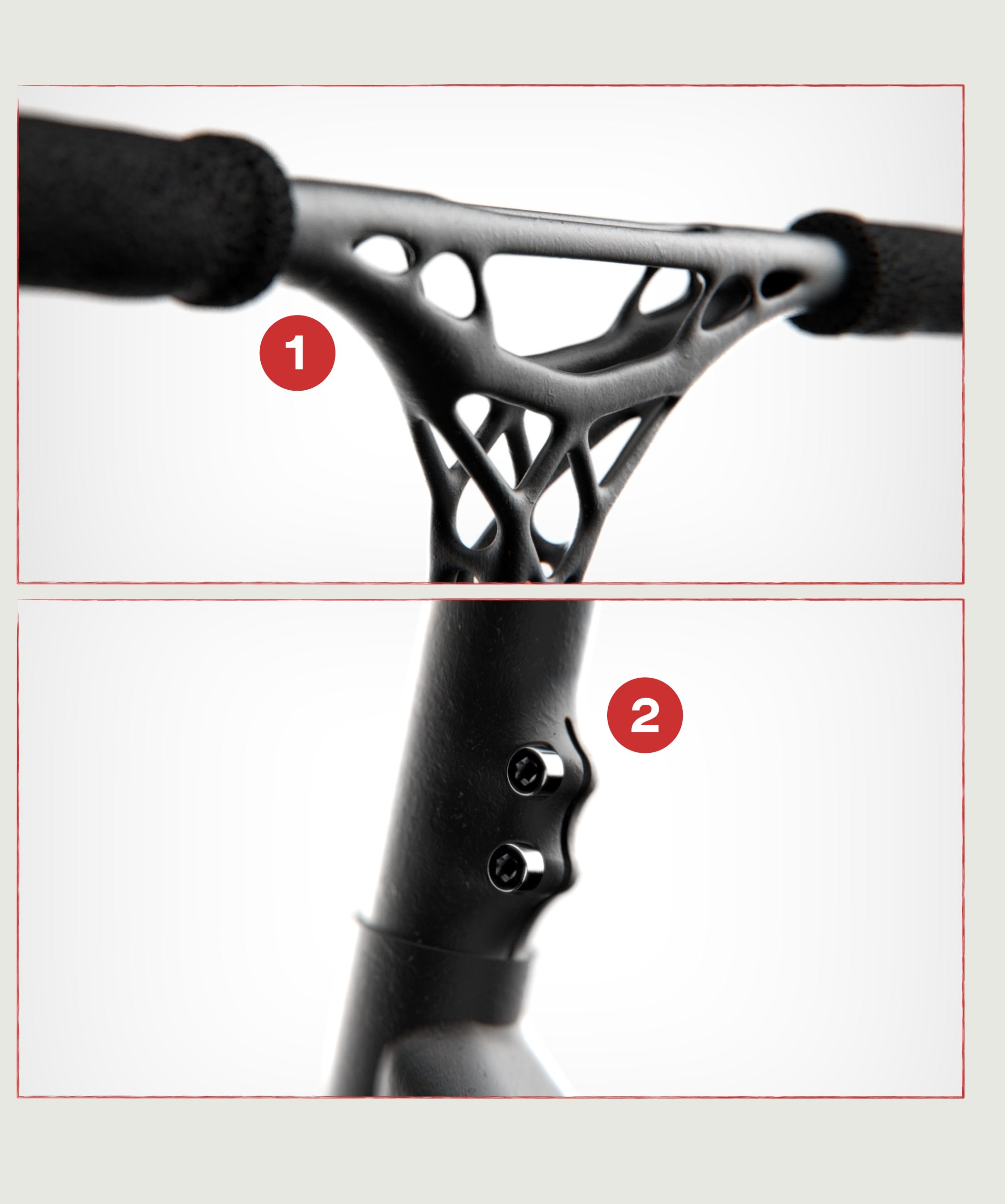
Handlebar, 692.22 g
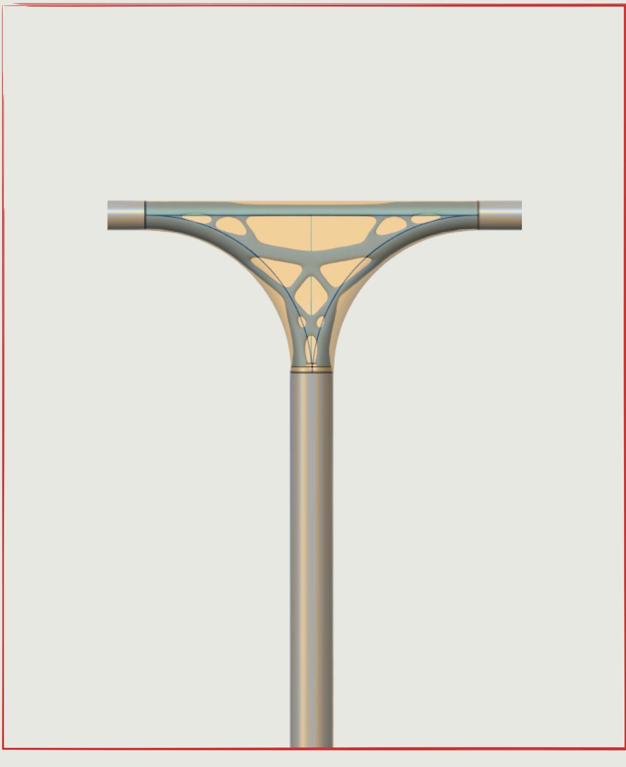
  1. Grip-to-handlebar junction as a formal gesture: an organic transition between the tube and the grips, resolved through continuous geometries derived from topology optimization and additive manufacturing.
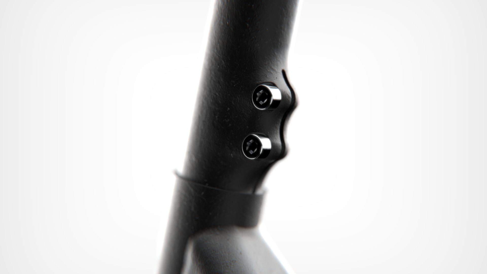
  2. Monobloc handlebar: the clamp is integrated into the handlebar as a single optimized part, cutting weight and component count and favouring a fluid, functional aesthetic.
The Void fork

Fork

Fork, 172.71 g
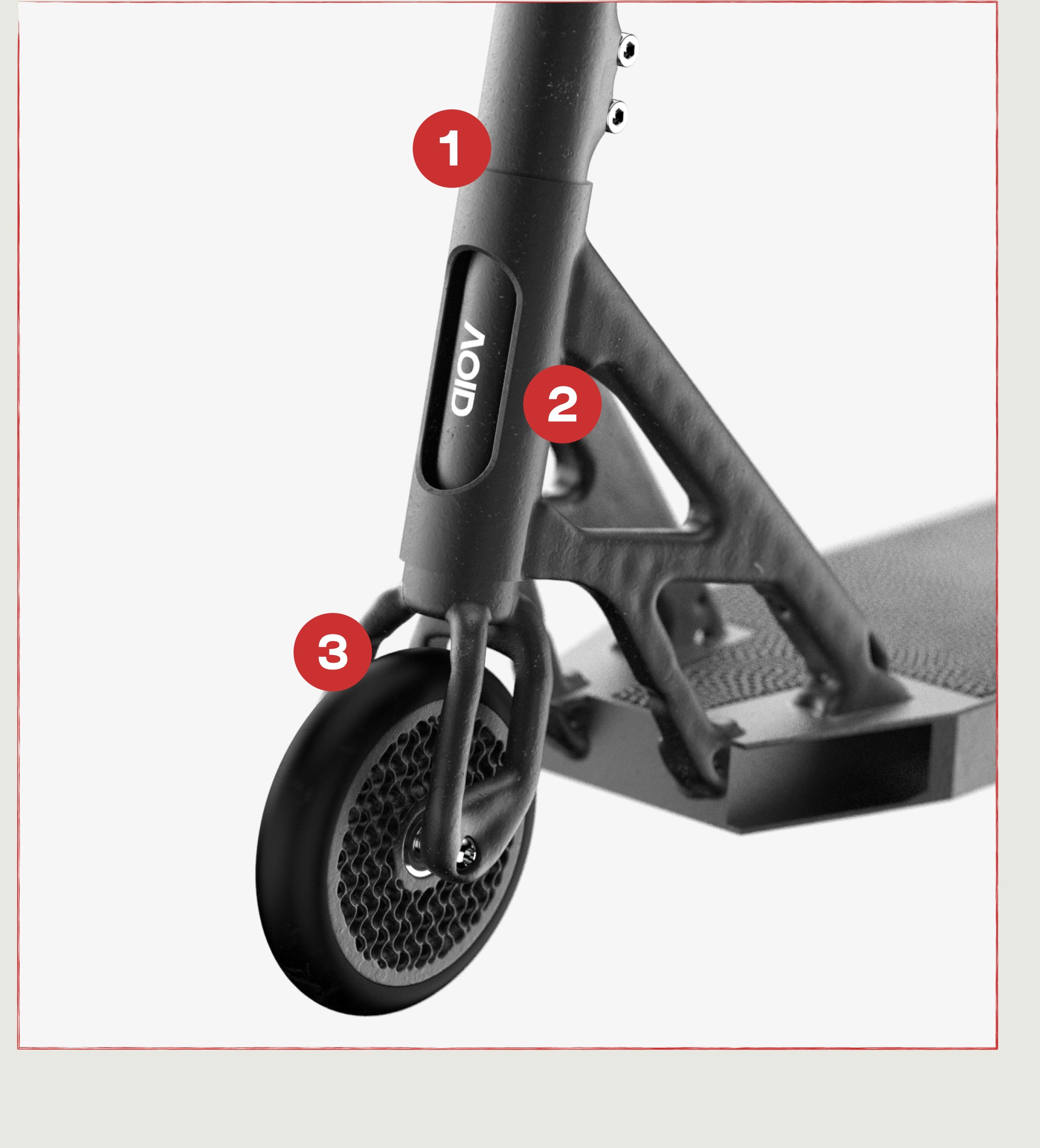
  1. Fork with an HIC system: an internal junction that guarantees rigidity and a clean aesthetic.
  2. Internal lattice with a gyroid structure: maximum mechanical strength with optimal weight reduction, thanks to its continuous geometry.
  3. Topologically optimized lower fork: 30% lighter while keeping rigidity and structural strength.
The Void wheels

Wheels

Wheels, 181.4 g
  1. Functional radial lattice: parametric geometry adapted to the load, optimized to cut mass while keeping structural rigidity. A technical, efficient visual identity that expresses lightness and performance.
The Void grips

Grips

Grips, 66.75 g x2
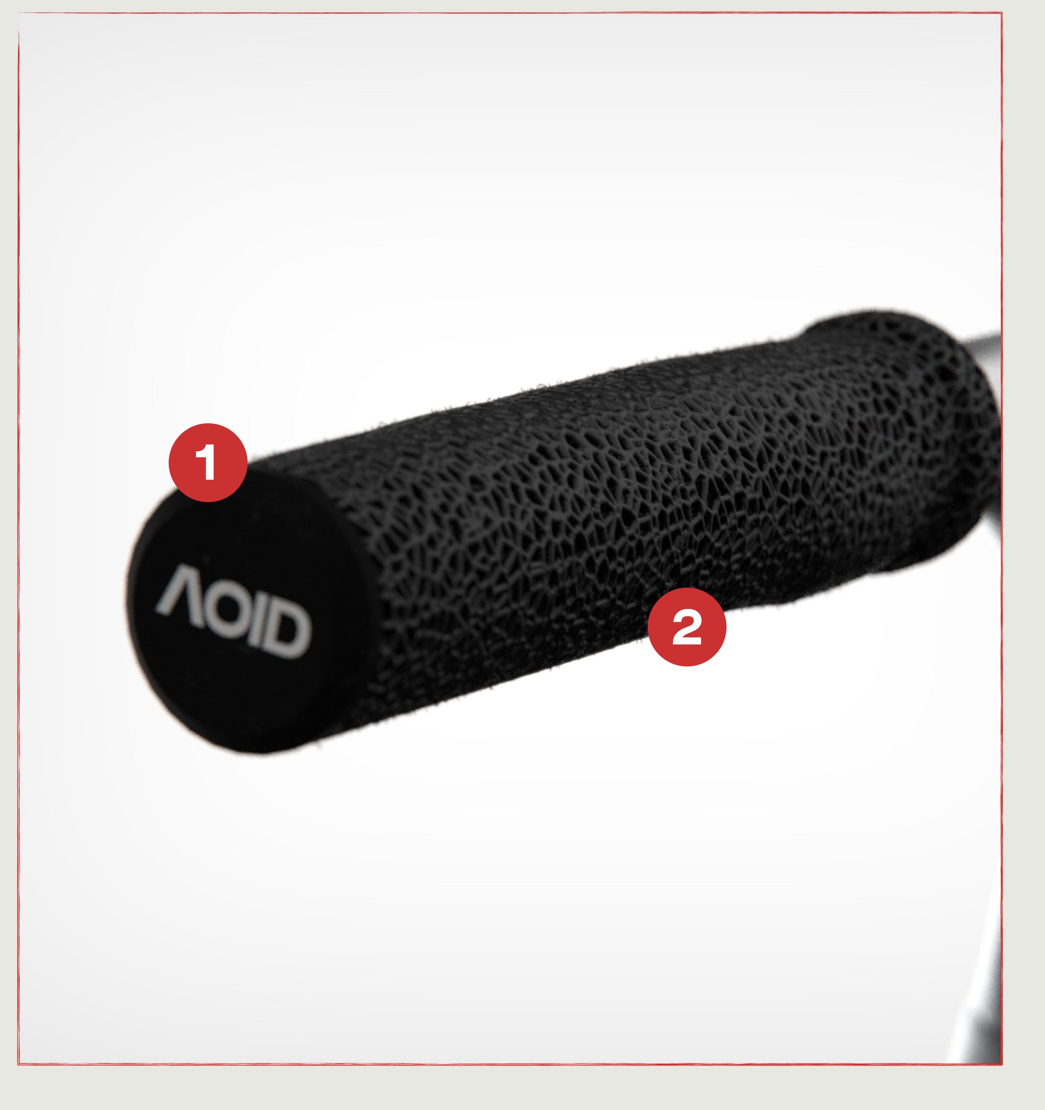
  1. Junction between the rigid outer zone of the grips and the flexible layer that provides the adherence, made in TPU — an ideal material for additive manufacturing, combining comfort and durability.
  2. Structure with a Voronoi lattice designed from the simulation of the forces the hand exerts when gripping.
Void — ride the void, the closing lockup

Gallery

The finished deck, logotype embossed in the printed surface
Handlebar and grip, printed as one optimized piece
The printed handlebar off the machine
The scooter against black
Three-quarter view of the complete scooter
The handlebar seen head-on
Deck and fork from behind
Fork clamp detail, HIC system
Grip end with the Void mark
Deck surface with its Voronoi texture
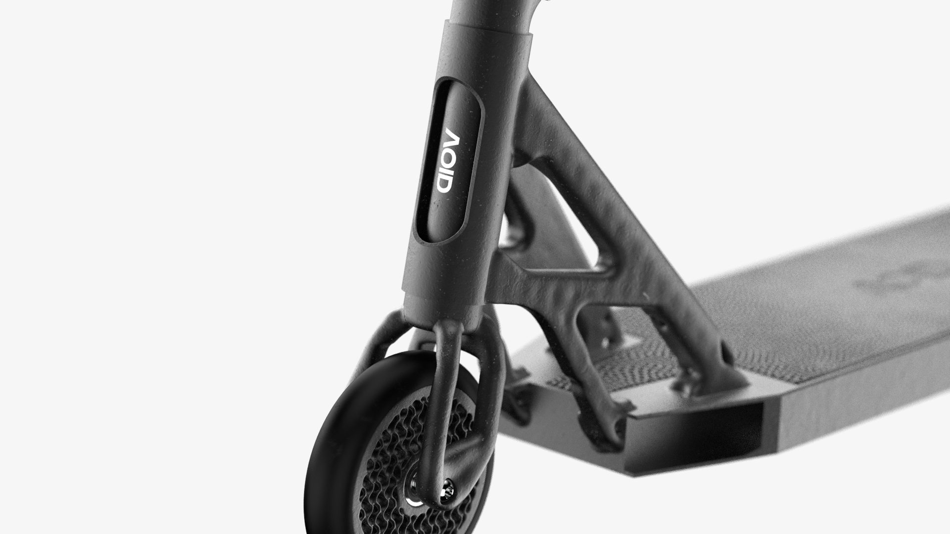
Front end: fork, wheel and deck junction
The lattice wheel
The lattice wheel
The complete scooter